Tonight, I replaced the 1µF capacitor. The right channel is still weak, but I had the feeling that is what less weak than before... Strange.
Anyway, it is still not good so I prepared a small test bench for the J-Fet.

I found ten 2SK170 coming from a Boozhound kit that I never built (I made a Pearl 2 instead). I'll test my test bench with them.
Anyway, it is still not good so I prepared a small test bench for the J-Fet.
I found ten 2SK170 coming from a Boozhound kit that I never built (I made a Pearl 2 instead). I'll test my test bench with them.
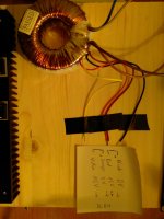
Hello, I am close to finishing my DCB1 build. Before I connect the board to the 50VA 2x15V transformator, however, I want to ensure that I did understand the wiring correctly. I connected the primary side in series due to the 230V system. I also connected the secondaries in series resulting in the three wires shown in the first picture. These three are connected to the DCB1, right? The connection in the middle serves as "center tap". Polarisation of the other two wires doesn't matter.
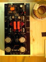
The second picture shows the finished DCB1 build. Is there anything you recognize as obviously wrong? I don't want to blow up all my work due to a stupid mistake") .
.
Thank you.
The second picture shows the finished DCB1 build. Is there anything you recognize as obviously wrong? I don't want to blow up all my work due to a stupid mistake
.Thank you.
Attachments
Stefan, I think it is for you to ask your question in the Salas hotrodded blue DCB1 build thread. People there are a lot more familiar with your board.... Is there anything you recognize as obviously wrong? I don't want to blow up all my work due to a stupid mistake
I just desoldered and test the J-Fets.
Q101: 0.816V

Q100: 7.98V

(R is 100.6 ohms)
Given what AndrewT said above,Q100's measure looks strange...
I also hav a question concerning the 2SK170. I remember that the one I got with the B1 kit had straight pins, but the other coming from the Boozhound kit have pins with two 90° angles, like on the picture below:

There was different versions?
Q101: 0.816V
Q100: 7.98V
(R is 100.6 ohms)
Given what AndrewT said above,Q100's measure looks strange...
I also hav a question concerning the 2SK170. I remember that the one I got with the B1 kit had straight pins, but the other coming from the Boozhound kit have pins with two 90° angles, like on the picture below:
There was different versions?
Last edited:
The 0.816Vdc across a 100r indicates 8.16mA when Vds = ~8.2Vds
The 7.98Vdc says it is broken, (79.8mA when Vds~1Vds)
BTW, that resistor will have been overheated, it was dissipating ~640mW. If you need to re-use, then do so in some non audio location and not for calibrating devices.
The 7.98Vdc says it is broken, (79.8mA when Vds~1Vds)
BTW, that resistor will have been overheated, it was dissipating ~640mW. If you need to re-use, then do so in some non audio location and not for calibrating devices.
Last edited:
OK. So I have to change Q100.The 0.816Vdc across a 100r indicates 8.16mA when Vds = ~8.2Vds
The 7.98Vdc says it is broken, (79.8mA when Vds~1Vds)
The Jfets from PassDIY are matched, so I presume I have to change the four 2SK170...
I measured the ten transistors from the Boozhound kit. There four matched at Id around 5.3mA and four other around 3.2mA. Is there an Id requirement for the B1?
The test was not long, but I'll put a new resistor on my test bench.BTW, that resistor will have been overheated, it was dissipating ~640mW. If you need to re-use, then do so in some non audio location and not for calibrating devices.
I have seen 2sk170 with straight pin (bulk packaging) as well
as the 'angled pins' (tape and reel packaging).
Thanks.The supplementary codes attached after the BL describe the package style.
k170s come in lots of different packakes and all are To92 and electrically the same.
jFETs are often manufactured with Drain and Source identical. This particularly applies to RF jFETs.
The 2sk170 and lsk170 are not intended for RF duty and the datasheets do not specify that they are symmetrical.
But when checking Idss and Id when Vgs is not zero, I find they seem to perform very similarly inverted at DC signal levels. It appears they are symmetrical.
If so, then it is valid to swap D & S.
Let me try it and see what i find outjFETs are often manufactured with Drain and Source identical. This particularly applies to RF jFETs.
The 2sk170 and lsk170 are not intended for RF duty and the datasheets do not specify that they are symmetrical.
But when checking Idss and Id when Vgs is not zero, I find they seem to perform very similarly inverted at DC signal levels. It appears they are symmetrical.
If so, then it is valid to swap D & S.
Hello All,
I just finished building my B1 using boards from the PassDiy store. I’ve tested it and it works 😊 but it’s just sitting on a piece of cardboard as I’m currently waiting on my chassis to come in from the DiyAudio Store. The rca jacks I am using are mounted on their own plastic plate and therefore will be floating and be isolated from the chassis. If I’m powering the B1 with a standard wall wart, and the power input barrel connector is also isolated from the chassis can I use insulated plastic stand-off’s to mount the board, or would it be best to use metal stand off’s? I’ve read through the build thread multiple times and I think I’m understanding from the posts on page 28 that I don’t need to ground the board to the chassis as I’m using a wall wart. Is this correct? Sorry, for asking what may be already answered. I just want my build to be as safe and noise free as possible. Thank you!
I just finished building my B1 using boards from the PassDiy store. I’ve tested it and it works 😊 but it’s just sitting on a piece of cardboard as I’m currently waiting on my chassis to come in from the DiyAudio Store. The rca jacks I am using are mounted on their own plastic plate and therefore will be floating and be isolated from the chassis. If I’m powering the B1 with a standard wall wart, and the power input barrel connector is also isolated from the chassis can I use insulated plastic stand-off’s to mount the board, or would it be best to use metal stand off’s? I’ve read through the build thread multiple times and I think I’m understanding from the posts on page 28 that I don’t need to ground the board to the chassis as I’m using a wall wart. Is this correct? Sorry, for asking what may be already answered. I just want my build to be as safe and noise free as possible. Thank you!
When I built my first B1, about 4 years ago, I used nylon standoffs to mount the board.
Thanks Jeff!
- Home
- Amplifiers
- Pass Labs
- B1 preamp build thread