Hi, I have not done enything yet. I can see on picture from underside print that one soldier point is litle different then the two adder legs. I wait for the new Jfets to arrive and solder them in with litle longer legs. So, the B1 is powered 24/7. But only signal when playing music. So the first hour I have no sound in right canal, but comes on and work until I turn off cd/dac or tv. But the sound is the best I ever hadd. The different from last B1 is regulated power (24v), ODAM 1 and 10 uF caps ( no bypass ) and Takman carbon film vs metal film in the atteunator ( the load resistor is Carcroft naked ).
Hi again, I have now solve the problem.
Did not want to do things before I got JFets from Jims Audio.
It takes time in this Corona times. Anyway, before I got the parts a friend wants to look at my Accuphase F-20. So I took it to him. Next day coming home, I rigg it together again. Turn system on, sound just in left canal. Then I bendt alitle on the RCA cabel out of B1, gess what, sound in right canal ( : Broken soldierpoint in RCA plug. So now I have stereo and 4 mathed 10mA JFets. Happy Weekend !!
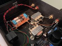
Playing around with a spare pair of Edcor 600:15k’s, and I thought it would be a nice time to revisit the B1 ‘original’. This was the very first piece of DIY gear I made, and I’ve always enjoyed its sound. This time I built it point to point on perfboard and put the Edcor’s after the B1 (ZM has me hooked on iron  ). Not much to look at, but it sounds really, really good! A quick, fun project to satisfy the DIY itch
). Not much to look at, but it sounds really, really good! A quick, fun project to satisfy the DIY itch Attachments

Funny you should ask. I'm running low on my regular, leaded solder, so I used up some of this fancy WBT lead-free crap I bought before i knew any better. I absolutely hate lead-free solder, but this was one of those 'solder and see' kinda projects
*edit* whenever I find the permanent home for these Edcor, they'll have to undergo a serious degunk job
*edit* whenever I find the permanent home for these Edcor, they'll have to undergo a serious degunk job
Last edited:

That's possible – it may be the 50R from the buffer cell and resistance after that. I've always used small values (or nothing) for that last resistor, fwiw. All I can say is that its driving the Edcor just fine from what I can hear. I do plan measuring distortion etc later on, and maybe that'll tell us something different.
make it zero - that series resistor
Codyt ....... situation with impedances is somewhat different
xformers are having nominal impedance value(s), which means they're having adequate inductivities and Rdc to comply with declared impedances, of preceding and following circuits
but! main function of xformer is to xform current, voltage and ratio between them, known as impedance ; there is also power xforming, but ignore that now; point being that impedances in circuit are going to be result of preceding and following impedances , of circuits surrounding xformer itself
so, we know that B1 is capable driving primary of 600R declared xformer
we have xformer connected as autoformer here
so, if autoformer is set to 6db gain , that means twice voltage
but - impedances are transformed in squares and roots of voltage ratios
so, if B1 is having Rout of 50R, autoformered for 6db, that means resulting Rout of B1T is 200R - still low enough
if we connect B1 to autoformer notch down (that's 150R tap of primary) , voltage ratio is 4 times (12db)
Rout goes 16 times ...... 50 x 16= 800R, still low enough , but I wouldn't use it to load harder than 47K or even better - 100K (amp having that Rin)
similar story goes backwards
if B1T with 6db gain see amp with Rin of 10K, that means that buffer sees load of 10K/4
if B1T with 12db gain see amp with Rin of 10K, that means that buffer sees load of 10K/16
so, things are slightly more complicated ......... but easy, when you're doing it for ooomphteenth time
Last edited:
- Home
- Amplifiers
- Pass Labs
- B1 Buffer Preamp