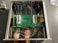
Nelson’s "B1 Buffer Preamp" document says the buffer can use an external PS from 18-24VDC. Whether a resistor change is necessary (w/24V) I cannot comment on.
Cheers
Cheers
Can I use B1 Buffer preamp 24 v ?
What advantage(s) do you find with running it at 24V?
Thanks, Pete
Thanks, Pete
Mine runs at 24v, never had an issue.
Ok, thanks. I was just curious if I should try 24V as well, even if your statement was just "you thought it sounded better". Obviously 24V has no detrimental effects in your experience. Wasn’t judging your use of 24V ….
Cheers, Pete
Cheers, Pete
Headroom?
Maybe lower distortion?
Feeling better running devices at higher voltages?
All of the above?
Do you see any disadvantages?
I personally don't.
What advantage(s) do you find with running it at 24V?
Thanks, Pete
No real advantage other than I needed 24v for my leach phono stage which is sharing the power supply. One of the inputs to my b1 is the leach which requires 24v.
What advantage(s) do you find with running it at 24V?
Thanks, Pete
This is a probably a question for Papa but will changing the voltage change the distortion spectrum? i.e. the proportions of 2nd and higher harmonics? Does it change the sound in that way? I have seen that the H2 device he designed to explicitly adust such a distortion mix was adjusted by tweking the supply voltage.
Imagine if you could have a tube B1 run at let's say 120 - 200 V.
Imagine the effortlessness and the drive that this will bring.
And the silky sound.
Imagine if you could have JFets doing the same, the clarity, the air.
Alas, both approaches have their limitations, so we take the middle ground - run SK170 (or SK369 in my case) close to their limits and not worry about semantics.
in post #4 underA friend of me will perform on his B1 (diy) some variation for additional enhancing the sound quality.
The article of his used preamp buffer is here:
PassDiy
He want to use a jFET for RF-applications instead the 2SK170. Mainly due the lower input capacitance around or even below only 5pF (2SK170 = 30pF input capacitance).
2N5484-5486, BF244, BF245, BF256, J304, J305 and 2N6908-6910 are examples.
Unfortunately Gm is very low. But there is the possibility for an extension of the circuit by a BjT - either as a normal darlington (Ultra High Zin Buffer) or Sziklai darlington (low capacitance wide band buffer) configuration - go to the NS application notes in the attachments.
In old publications sometimes incorrectly called as a cascode - go for desription of the circuit of third pdf to page 58 of last pdf.
Are there any experiences in modification steps like this ?
Maybe between R102 resp. 103 and R2/R3 an additional pot is necessary for adjust the center voltage.
Thank you for comments.
More FET noise measurements (for EUVL)
are some interesting hints.
also of interest in this case are this threads:
Some other Source Follower Configurations
B1-Turbo on a Chip
NJFETs for Source Follower Applications
https://www.diyaudio.com/forums/sol...mance-source-follower-module.html#post2336629
https://www.diyaudio.com/forums/hea...ltra-low-noise-suggestions-3.html#post5606660 (post #25-30)
B1 JFET alternatives list
https://www.diyaudio.com/forums/sol...e-low-noise-amplifier-lna-13.html#post2192239
Ultra low noise amp with JFET's - How to reduce the THD ??
IF3601 IF3602 Ultra Low Noise JFETs
Last edited:
Hi, I have now played for 3 days.
But last night I lost sound i right speaker.
I tapped the Jfets in right canal, sound come back for awhile. Then lost it again.
1- Can it be that the Jfets is overstressed (damage) because I use 100R as output resistor and my crossover is at 20K (next after B1)?
2- Can it be that I have put my Jfets very close to PCB ( short legs ), and damage them then solder them ?
Frank
- Home
- Amplifiers
- Pass Labs
- B1 Buffer Preamp
