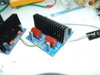
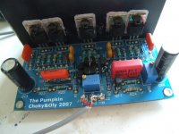
My Pumpkins
In my opinion, I've used good components where required.
Any comments about the odd noises would be much appreciated.
The cheap - tacky - screened leads were just there for testing.
All resistors were 1% Metal Film types.
All matched semi-conductors were supplied by ZenMod himself.
In my opinion, I've used good components where required.
Any comments about the odd noises would be much appreciated.
The cheap - tacky - screened leads were just there for testing.
All resistors were 1% Metal Film types.
All matched semi-conductors were supplied by ZenMod himself.
Attachments
Last edited:
Does the B1 have any DC blocking?
Its got 1uF at the input and 10uF at the output.
http://www.passdiy.com/pdf/B1 Buffer Preamp.pdf
Puffin. Look at the schematic. Note that the B1 uses a single polarity power supply. Note also the two capacitors as mentioned by Katie's Dad. The input signal sweeps either side of Zero Volts. The output signal sweeps either side of Zero Volts. The B1 (amplifier) can only operate with voltages above Zero Volts. The capacitors block the voltage discrepancies at the input and at the output. Since many of the Pass Power Amps are direct coupled, the B1 is ideal for not passing DC errors through to the speakers.
Last edited:
rCRCRC.
The first r is the sum of the resistances of the secondaries + the rectifier leadouts, plus the wiring leading to the smoothing caps. It might only be 0r05 in total for your flow and return route, but "r" has a filtering effect and that effect is not zero
When you don't use cascaded filtering stages and instead use (a single or bank of) C alone, then the filter is actually rC.
I understand the reason not to pass DC after the poweramp to the speakers, but what is the purpose of mantaining a DC-free path until the poweramp? Does it affect the source, dac, preamp and so in any way? Will it degrade the sound? Are speakers the only damageable item or having a pair of DC volts can affect previous stage's electronics?Puffin. Look at the schematic. Note that the B1 uses a single polarity power supply. Note also the two capacitors as mentioned by Katie's Dad. The input signal sweeps either side of Zero Volts. The output signal sweeps either side of Zero Volts. The B1 (amplifier) can only operate with voltages above Zero Volts. The capacitors block the voltage discrepancies at the input and at the output. Since many of the Pass Power Amps are direct coupled, the B1 is ideal for not passing DC errors through to the speakers.
Thanks! Merry christmas to all!
Hi,
DC in the audio stream is generally not desirable.
If it's only 1mVdc on a signal of 10Vac, you can safely ignore it think that is so, but I am not a designer.
If it's 10mVdc on a signal of 100mVac, then it may stop the amplifier stage from working at all.
Or it may cause early clipping of the signal passing through, or it may increase the distortion added to the signal as it passes through.
You must be aware of that DC to AC ratio. It is critical to allowing High Fidelty signal processing.
BTW,
why did you break Forum Rule and quote the whole of my post?
Thank you.
Puffin. Look at the schematic. Note that the B1 uses a single polarity power supply. Note also the two capacitors as mentioned by Katie's Dad. The input signal sweeps either side of Zero Volts. The output signal sweeps either side of Zero Volts. The B1 (amplifier) can only operate with voltages above Zero Volts. The capacitors block the voltage discrepancies at the input and at the output. Since many of the Pass Power Amps are direct coupled, the B1 is ideal for not passing DC errors through to the speakers.
__________________
regards Andrew T.
I never like to assume and so the question was asked. Thnks for confirming what I thought I knew

I discovered that it is forbidden to talk about "CRT related things"...but anyway, it was a good trick to get me reading the forum rules thoroughly for the first time
BTW, why did you break Forum Rule and quote the whole of my post?
AndrewT, I have a question regarding this -- I read the forum rules, here:
http://www.diyaudio.com/forums/site-announcements/167561-diyaudio-rules.html
And don't see what you are referring to when you say that quoting an entire post is against the rules. Would you please supply a link to the relevant page? Thanks.
~~~
Back to the topic -
The B1 has sufficient DC blocking due to the input and output caps. Of course, capacitors are always a subject of discussion and debate, and you may of course use whatever type you choose.
If you would like to not use them there is a circuit for that, I believe it's the 'DCB1' or 'Mezmerize'.
http://www.diyaudio.com/forums/everything-else/203174-real-apology-andrew-t.htmlAndrewT,....... Would you please supply a link to the relevant page? ..........
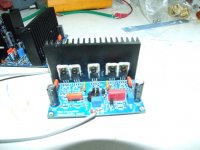
OK its back to basics with the Pumpkins.
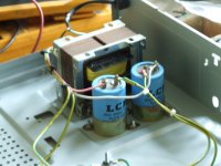
It doesn't get more basic than a 100VA 32-0-32V transformer, a Bridge Rectifier and 2 x 4700uF Caps.
One question.
Off load the unreg supply is approx 42-0-42V DC.
The Pumpkins are nominally 36-0-36V.
If I resistor load the PSU with 500R 100W resistor then it drops to approx 36-0-36V (as intended). - Across the + - - (84V DC) = 170mA
What is the quiescent current of (1) Pumpkin - I am testing them individually.
ZenMod tests the Shuntkys at 80mA each.
Attachments
hi KatieandDad,
you are really fast!
my recommendation with 32V was thought for use with 7915 and 7815 with the scheme I sent you...
I think it is better to have the regulation, you can then choose between +-15V to +-36V for all pre´s!
I suggest you buy locally the regulators....
you are really fast!
my recommendation with 32V was thought for use with 7915 and 7815 with the scheme I sent you...
I think it is better to have the regulation, you can then choose between +-15V to +-36V for all pre´s!
I suggest you buy locally the regulators....
hi KatieandDad,
you are really fast!
my recommendation with 32V was thought for use with 7915 and 7815 with the scheme I sent you...
I think it is better to have the regulation, you can then choose between +-15V to +-36V for all pre´s!
I suggest you buy locally the regulators....
The Pumpkins run at +/- 36V.
I've got the 7915 and 7815 regulators, don't you think the transformer will put their inputs a bit close to their limits.
I'm not sure that the Pumpkins will run properly as low as +/- 15V.
- Home
- Amplifiers
- Pass Labs
- B1 Buffer Preamp