The B1 is pretty immune to voltage variations as it stands.
You could put a 10V zener in place of R3 which might add a bit of noise to the otherwise silent B1.
As you suggest, a 1mA CCS would work but I don't think it's necessary.
I just drive mine from a 22V LM317 regulated supply. I've said it before - The silence is BLACKER than BLACK and the fidelity is just magical.
Just using a CRC supply was also SILENT.
Using a high impedance Capacitive Multiplier in place of the CRC did show a minor reduction in dynamics, hence my change to a decent 30VA transformer and CRC.
PSU noise was NEVER an issue though.
Last edited:
Has anyone tried to clone the diagrams that Nelson has posted on the PassDIY site ?
If you look carefully there is a discrepancy between the PCB layout and the schematic.
On the schematic C3 is connected between 0V and Vcc/2.
On the PCB one end of C3 is connected to Vcc.
Which one is right ? Should C3 be across C2 or across D1 ?
I got a personal e-mail from Nelson - It doesn't matter where C3 is placed. He stated that he just liberally applies bypass caps after he has drawn the basic scematic.
As it stands C3 on my board is across D1 (ie the PCB is correct) and I've also bypassed C2 (the schematic version).
The B1 is pretty immune to voltage variations as it stands.
PSU noise was NEVER an issue though.
As tscharma has shown, the circuit does in fact change a lot with differences in applied DC voltage. The distortion changes by a factor of 2 with a doubling of the supply voltage, for example.
The current limiting diode in place of Q101/Q201 is a better choice because you don't have to select from a pile of 2SK170's to find one that gives you the desired current. The CLD's are calibrated in milliamps already and they are exactly the same kind of circuit as Q101/Q201.
The only reason that PSU noise has not been a problem is because of the brute force employed by C1 and C2. Fifteen thousand microfarads is something you use in a power amplifier, not generally in a little line level buffer. There are more elegant ways to do this.
What I need to find out is the intended bias point for Q100/Q200. I can't tell from the schematic and it may be because I am not an expert at electronics like some others.
You could put a 10V zener in place of R3 which might add a bit of noise to the otherwise silent B1.
.
The capacitors C2 and C3 in the schematic would silent any noise produced by a zener. It is common to bypass zener diodes with small value capacitors to make them silent. If a zener was used you wouldn't even need the 15,000uF C2.
The only advantage that I can see from the all passive brute force method employed here is that the bias goes up and down with changes in the power supply voltage, which I assume keeps Q100/Q200 at about the same operating point, though I'm not sure that's possible because of the constant current arrangement of Q101/Q201.
Last edited:
The capacitors C2 and C3 in the schematic would silent any noise produced by a zener. It is common to bypass zener diodes with small value capacitors to make them silent. If a zener was used you wouldn't even need the 15,000uF C2.
Let's see if Nelson comments here.
The standard B1 is excellent - no-one would be brave enough to say that it cant be bettered but it is beautiful as it stands.
Sometimes BRUTE FORCE works, and in the case of the B1 it certainly does.
I use mine with a regulated supply so the issue doesn't arise.
I'll be interested to see how your experiments pan out.
OK, thanks. I don't yet have fancy test gear to find out though.
Nelson does like KISS (Keep It Simple Stupid).
With my CRC supply + C1 and C2 on the B1 I've got over 40000uF of caps in the supply line.
For a unity gain Buffer that is INSANE.
Nearly as crazy as the 1.5F (yes Farads) that I've got in the Aleph 4 that follows it.
OK! it seems I've stepped in some doo-doo on this thread by suggesting something a little different. Sorry!
Can someone measure the voltage across Q100/Q200 at a specified rail voltage? I'm still scratching my head about this...
OK! it seems I've stepped in some doo-doo on this thread by suggesting something a little different. Sorry!
Can someone measure the voltage across Q100/Q200 at a specified rail voltage? I'm still scratching my head about this...
Sorry I cant get probes into mine because of the huge Obligatto caps.
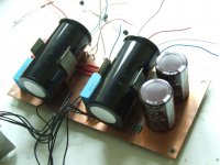
Attachments
The only reason that PSU noise has not been a problem is because of the brute force employed by C1 and C2. Fifteen thousand microfarads is something you use in a power amplifier, not generally in a little line level buffer. There are more elegant ways to do this.
If I was to make a completely gold-plated B1 I would probably use this PSU - http://www.amb.org/audio/sigma11/ Just because it's cool.

I think that the stock circuit was designed with the huge filter capacitance to give lots of leeway to what DC power supply you can successfully use... Being a DIY design, the designer made some allowances in order to give a greater chance of success to the builders. Some people will make discrete regulated supplies, some people will use batteries, the commercial version was shipped with a SMPS brick. It can be successfully (and quietly) run from an unfiltered cheap wall wart.
There is no doubt that a more elegant supply could be made. But ultimately, would it be 'better'?
Last edited:
It really doesn't need a Rolls Royce PSU.
If you want to skimp on C1 and C2 and spend your money on a PSU then that is up to you.
In its basic format it works perfectly with a CRC PSU. I use 18V Transformer and a standard W001 bridge with 4700uF 2R2 4700uF which is probably OVERKILL.
If you want to skimp on C1 and C2 and spend your money on a PSU then that is up to you.
In its basic format it works perfectly with a CRC PSU. I use 18V Transformer and a standard W001 bridge with 4700uF 2R2 4700uF which is probably OVERKILL.
Are you serious?OK! it seems I've stepped in some doo-doo on this thread by suggesting something a little different. Sorry!
Can someone measure the voltage across Q100/Q200 at a specified rail voltage? I'm still scratching my head about this...
Look at the schematic. The answer, 9V, is there.
Are you serious?
Look at the schematic. The answer, 9V, is there.
Are you certain of that ?
Q101/Q201 are acting as CCS
Q100/Q200 are the buffers.
It really doesn't need a Rolls Royce PSU.
If you want to skimp on C1 and C2 and spend your money on a PSU then that is up to you.
In its basic format it works perfectly with a CRC PSU. I use 18V Transformer and a standard W001 bridge with 4700uF 2R2 4700uF which is probably OVERKILL.
True, it does not need a Rolls Royce PSU, but you should hear one(DCB1) first before speaking of quality of sound or lack there of. Too many presumptions!
Are you serious?
Look at the schematic. The answer, 9V, is there.
The bias voltage is exactly 9 volts, from the 10k/10k divider, of course. That doesn't tell me what the operating point is though. I don't know Vgs or Vds, for example. The amount of current set by the lower jfet is also unknown, and it can apparently vary over 3 milliamps depending on which particular transistor you stick in there.
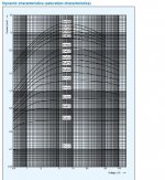
It may be best to just stick with the CC jfet instead of a CC diode, since the current regulation of the higher value CCD's are not that great. I don't know if a strapped jfet is any better, since these CCD's are basically strapped jfet's anyway. It's better to use a smaller value CCD apparently since the current regulation with changes in voltage is better.
Attachments
True, it does not need a Rolls Royce PSU, but you should hear one(DCB1) first before speaking of quality of sound or lack there of. Too many presumptions!
I think I'd like to replace C1 with an 18V zener, bypassed with 0.1uF capacitor, and select R1 based on the supply voltage. Then I can replace R2 with a 0.9mA CCD and replace C2 with another 0.1uF capacitor. The bias circuit draws essentially zero current so there's no need for a huge capacitor there. I assume Mr. Pass picked 18volts for the supply for a reason and not just randomly.
Vgs of both jFETs is exactly zero volts. That's the purpose of selecting the jFETs to have the same Idss. Run a jFET at exactly 100% of Idss and the Vgs must be zero volts.
Put that in and you'll see that the source of the upper jFET and the Drain of the lower jFET are at exactly 10k/(10k+10k) * +18Vdc, i.e. 9V
Put that in and you'll see that the source of the upper jFET and the Drain of the lower jFET are at exactly 10k/(10k+10k) * +18Vdc, i.e. 9V
Last edited:
There is no doubt that a more elegant supply could be made. But ultimately, would it be 'better'?
Well, since the distortion changes a lot with supply voltage, I'd guess that it'd be important to keep it constant. The brute force method is one way. I may have a very good +/- 32V power supply available for a previous stage, so maybe I could feed that to this buffer and use R1 to reduce the voltage to 18. It's an idea anyway.
- Home
- Amplifiers
- Pass Labs
- B1 Buffer Preamp