I am sure your findings are valid in your circuimstances. I think for opamps if they are not implemented correctly then they don't sound as good. That was why I suggested a high quality shunt reg. By the way, even with a very good shunt reg, proper implementation is critical for achieving the result.
For sure, 2sk170 is a lot cheaper, and it sounds good, and the jFET XO proposed in this thread is excellent. By all means go for it and have fun.
I was only suggesting that the best opamps are at least as good or better, if implemented properly with a very good regulator. (I used the same regulator, same layout when I compared the opa627 to the B1).
Well I've "finalized" (if that is possible) my crossover design and since it has departed completely from Jacques' original design I'm not posting it here. But if anyone is interested in what I came up with it is posted in my blog It still uses B1's but not for the actual filter elements.
Thanks to Jacques for starting this thread because it was the catalyst I needed to come up with my own design") not only in getting me thinking, but also in deciding to take the plunge and learn how to use spice!
not only in getting me thinking, but also in deciding to take the plunge and learn how to use spice!
Cheers,
Tony.
Thanks to Jacques for starting this thread because it was the catalyst I needed to come up with my own design
not only in getting me thinking, but also in deciding to take the plunge and learn how to use spice! Cheers,
Tony.
I like this idea for a x-over to add to my Aleph J-X amp
I like this Project for the B1-x-over, I am currently building my Aleph J-X amplifier and it will require a 100Hz high pass x-over that will not dimminish the quality of the sound, I believe that all the x-overs using integrated op-amps circuits will ruin the quality of the sound in my system that I have so carfully assembled for state of the art sound quality.
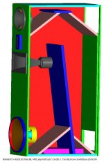
Picture is of my speakers which require a 100Hz x-over between the 18in JBL2242 in a 14ft transmission line labyrinth(low frequency optimized backwave-frontwave cancellation is 20Hz) and a 12in JBL2202 mounted in a short backwave horn for use between 100Hz and 500Hz, from 500Hz to 4KHz I have a 1.75in titanium diaphram JBL2525 compression driver horn loaded, and above 4KHz a Foundtek 98db per watt 5inch ribbon. My speakers efficientcy is 98db per watt 100Hz to 40KHz which requires the quality of the B1 x-over, below 100Hz I am using a sub harmonic synthizer 26-100Hz.
I like this Project for the B1-x-over, I am currently building my Aleph J-X amplifier and it will require a 100Hz high pass x-over that will not dimminish the quality of the sound, I believe that all the x-overs using integrated op-amps circuits will ruin the quality of the sound in my system that I have so carfully assembled for state of the art sound quality.
Picture is of my speakers which require a 100Hz x-over between the 18in JBL2242 in a 14ft transmission line labyrinth(low frequency optimized backwave-frontwave cancellation is 20Hz) and a 12in JBL2202 mounted in a short backwave horn for use between 100Hz and 500Hz, from 500Hz to 4KHz I have a 1.75in titanium diaphram JBL2525 compression driver horn loaded, and above 4KHz a Foundtek 98db per watt 5inch ribbon. My speakers efficientcy is 98db per watt 100Hz to 40KHz which requires the quality of the B1 x-over, below 100Hz I am using a sub harmonic synthizer 26-100Hz.
Attachments
Hello Jacques,
I am a little late to this thread. Have you built the LR2 circuit that you posted in Post #24.
If you did what were the results? I have a bag full of 2SK170’s and would like to build one of the same.
DT
All just for Fun!
No, I'm afraid I haven't as I've been extremely busy since the beginning of the year. I started to collect some parts but haven't been able to get to it yet :-(. I believe that a few folks on this thread have built that, or some variation on it.
Has anyone built the circuit in Post #1?
I read about the stop band issue in Post #4, however it looks like 50db down.
Would that be even audible to anyone? Are people concerned about phase issues?
I'm thinking about building a simple buffered salen-key circuit, like Nelson describes in other posts, perhaps the simpler circuits are the B? series buffers.
Thanks.
4th order B1 buffer crossover Calcs
I am trying to put together a stereo 2 way 4th order crossover with preamp source switching (2 sources) and overall volume control.
I have a pair of Snell E with a crossover point of 2700 Hz.
To configure the values for this cross point I referred to the Grey Rollins' article: The Xenover - Part II Article And Design By Grey Rollins
The resister and capacitor numbers corresponds to Grey's Schematics as indicated. I don't have a way to change the values on the attached PDF.
Butterworth high pass (Schematic 7)
C = C1 = C2 = C3 = C4 =.002
1st section: R5 = 0.9239/(2*Π*F*C) = 27.2k
1st section to ground: R6 = 1.0824/(2*Π*F*C) = 32k
2nd section: R11 = 0.3827/(2*Π*F*C) = 11.3k
2nd section to ground: R12 = 2.6130/(2*Π*F*C) = 77k
Butterworth low pass (Schematic 8)
R = R5 = R6 = R12 = R13 = 22k
1st section: C1 = 1.0824/(2*Π*F*R) = .0029 uF
1st section to ground: C2 = 0.9239/(2*Π*F*R) = .00247 uF
2nd section: C3 = 2.6130/(2*Π*F*R) = .007 uF
2nd section to ground: C4 = 0.3827/(2*Π*F*R) = .001 uF
As I proceed with buying the resisters and capacitors I would like confirmation that those calculations will work for the B1 buffer crossover using 2SK170BL devises. I may use a discrete opamp for the preamp gain stage.
Attachments
Values
Thanks Andrew,
I take it the calculations are correct for this buffer crossover.
I will buy a 100ea 1000pF caps and some other values that can be paralleled to achieve the values above. I have a capacitor meter for matching. This will be perfboard construction so I can do what ever necessary to reach the values.
Thanks for the help.
Rush
Whatever happened to this design?
If you are referring to me, I am busy with other projects, but will get to this project this year. I hope.
Rush
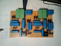
Phono Pre Amp B1 Crossover Complete
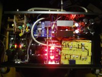
Finally finished the 2 Hypnotize regulators for the 2 way stereo crossover, had to cut off the B1 part of the boards to save space. I populated the bread board crossover 6 months ago, the Salas Simple phono pre amp and regulators were finished 2 months ago along with the Mesmerize DCB1. Put it all in the box, cranked it up on the bench and noted the DC offset of around .2 volts on each output. I chose to cap couple the output and not deal with rematching jfets. The high pass was a small .02 uF styrene cap, the low pass I used a 7 uF Kimber cap that was lying around, I may change this later as I only need a 1 uF and can afford a better cap in this value.
Hooked up the bench tube amp and crappy speaker and found a loud buzz on all the crossover outputs. So I took a .22 uF cap, attached one end to ground and started poking around the crossover. Found that when I touched the top leg (plus rail) of the top jfet on the input buffer, the buzz went away completely. That was easy, needed a little decoupling. Soldered them in and it is pretty quiet.
Listening now for the last hour or so and it sounds great! I am sure the parts will break-in over the next few weeks. I will leave it on.
I have a separate box for the 2 power transformers each is switched so if I don't want to listen to records, I can leave that transformer off and reduce heat and electricity consumption. Needed 2 transformers as the voltages were completely different.
I wired the transformer box to the pre amp with a 4 conductor cord and 4 pin XLR, each rectified raw voltage (48 VC and 17 VDC +/-) shares the same ground wire. Wasn't sure that was going to work and I worried about how I was going to ground all that in one pre amp box.
Worked it out with some fiddling.
Thank you Jacques Merde for all the help. This thread has given me a great sounding crossover.
I will also thank Salas for his regulators are everywhere, 8 of them in one box! (5 positive and 3 negative)
Rush
I am trying to put together a stereo 2 way 4th order crossover with preamp source switching (2 sources) and overall volume control.
I have a pair of Snell E with a crossover point of 2700 Hz.
To configure the values for this cross point I referred to the Grey Rollins' article: The Xenover - Part II Article And Design By Grey Rollins
The resister and capacitor numbers corresponds to Grey's Schematics as indicated. I don't have a way to change the values on the attached PDF.
Butterworth high pass (Schematic 7)
C = C1 = C2 = C3 = C4 =.002
1st section: R5 = 0.9239/(2*Π*F*C) = 27.2k
1st section to ground: R6 = 1.0824/(2*Π*F*C) = 32k
2nd section: R11 = 0.3827/(2*Π*F*C) = 11.3k
2nd section to ground: R12 = 2.6130/(2*Π*F*C) = 77k
Butterworth low pass (Schematic 8)
R = R5 = R6 = R12 = R13 = 22k
1st section: C1 = 1.0824/(2*Π*F*R) = .0029 uF
1st section to ground: C2 = 0.9239/(2*Π*F*R) = .00247 uF
2nd section: C3 = 2.6130/(2*Π*F*R) = .007 uF
2nd section to ground: C4 = 0.3827/(2*Π*F*R) = .001 uF
As I proceed with buying the resisters and capacitors I would like confirmation that those calculations will work for the B1 buffer crossover using 2SK170BL devises. I may use a discrete opamp for the preamp gain stage.
Finally finished the 2 Hypnotize regulators for the 2 way stereo crossover, had to cut off the B1 part of the boards to save space. I populated the bread board crossover 6 months ago, the Salas Simple phono pre amp and regulators were finished 2 months ago along with the Mesmerize DCB1. Put it all in the box, cranked it up on the bench and noted the DC offset of around .2 volts on each output. I chose to cap couple the output and not deal with rematching jfets. The high pass was a small .02 uF styrene cap, the low pass I used a 7 uF Kimber cap that was lying around, I may change this later as I only need a 1 uF and can afford a better cap in this value.
Hooked up the bench tube amp and crappy speaker and found a loud buzz on all the crossover outputs. So I took a .22 uF cap, attached one end to ground and started poking around the crossover. Found that when I touched the top leg (plus rail) of the top jfet on the input buffer, the buzz went away completely. That was easy, needed a little decoupling. Soldered them in and it is pretty quiet.
Listening now for the last hour or so and it sounds great! I am sure the parts will break-in over the next few weeks. I will leave it on.
I have a separate box for the 2 power transformers each is switched so if I don't want to listen to records, I can leave that transformer off and reduce heat and electricity consumption. Needed 2 transformers as the voltages were completely different.
I wired the transformer box to the pre amp with a 4 conductor cord and 4 pin XLR, each rectified raw voltage (48 VC and 17 VDC +/-) shares the same ground wire. Wasn't sure that was going to work and I worried about how I was going to ground all that in one pre amp box.
Worked it out with some fiddling.
Thank you Jacques Merde for all the help. This thread has given me a great sounding crossover.
I will also thank Salas for his regulators are everywhere, 8 of them in one box! (5 positive and 3 negative)
Rush
Attachments
Last edited:

Removed the output caps
I was in a hurry to finally listen to the pre amp/crossover after debugging it. I threw those caps on the output and did some listening.
But of course I can't leave well enough alone. I remeasured the DC offset and found none, .001, .003, .002, .000 and said what? I must have measured wrong or after 24 hours of burn in it settled out? Naw, I must have measured wrong. I didn't remeasure the offset after I added the caps to the plus rail, could be that, or?
Anyway, took the coupling caps out and hooked it back up. Sounds even more better without the caps. I guess you can hear caps.
I am an amateur after all.
That saved me a ton of money. The V-Caps TFTF were going to set me back a couple of large ones!
Might still buy them for the phono pre, but not at this time. I'll wait for Christmas, buy them tell the wife they cost half what they did and she can give them to me for Christmas. Then I won't have to buy her so large a present in return.
That has served me well for 19 years of marriage.
Rush
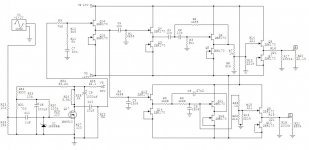
How does the attached circuit look like?
It's a Bride of Zen feeding a passive RC shelving lowpass followed a 3rd (cascaded 1st and 2nd) order high-/lowpass network employing unity gain DCB1 buffers.
I have the BOZ, a ready-made DCB1 blue edition, a DCB1 Mezmerize pcb and numerous pairs of matched 2SK170BLs. The additional JFET buffers would thus be fed from the DCB1s' shunt regulators.
With the present values the passive BSC should give a pot-adjustable attenuation past 500Hz for baffle step equalization.
The part values of the crossover that follows the BSC are based on matched capacitor values I happen to have on hands, and it's supposed to be a spread frequency crossover at 2500 and 3500 Hz. Level setting pots are provided for each branch.
What would you change, add, ditch? More gate stoppers perhaps? Supply decoupling caps I would certainly add in the real design then. Something else?
I also have one of those red JBOZ pcbs from ebay, which means i could build enough amp and buffer stages to move the gain stages to the output. JBOZ for highs, BOZ for lows, with JFET input buffer. Would that be preferable?
And does anyone have a link to that version of the JBOZ with the bipolar supply, please? I can't seem to find it.
Thanks for your critique,
Dave
Attachments
2sk170 gain stage
I managed to find the 2sk170 gain stage myself:
http://www.diyaudio.com/forums/pass-labs/146310-bf862-preamp-6.html#post2669699 and http://www.diyaudio.com/forums/pass-labs/146310-bf862-preamp-6.html#post2670449
Maybe I'll mod the DCB1's shunts to produce the appropriate voltages and use one of these circuits as a gain stage.
Now the question...gain stages at the input or the output?
- Status
- This old topic is closed. If you want to reopen this topic, contact a moderator using the "Report Post" button.
- Home
- Amplifiers
- Pass Labs
- B1 Active Crossover