Thanks Manfred ") I've been having some fun with ltspice (which I've only just started to learn), not getting particularly useful results, but I suspect that is more the user than the program I'll see how I go with the one you have posted, I suspect I really need to just build some stuff and measure it!
I've been having some fun with ltspice (which I've only just started to learn), not getting particularly useful results, but I suspect that is more the user than the program I'll see how I go with the one you have posted, I suspect I really need to just build some stuff and measure it!
Tony.
I've been having some fun with ltspice (which I've only just started to learn), not getting particularly useful results, but I suspect that is more the user than the program I'll see how I go with the one you have posted, I suspect I really need to just build some stuff and measure it!Tony.
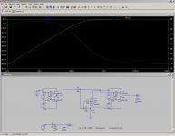
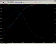
Well I've done a lot of reading, brushed up on my algebra, played with ltspice a lot, and finally modeled something that I think might be workable. My planned crossover freq is 200Hz. (which seems to be right as the curve is down just over 6db at 200Hz).
Screen shot of the results of comparing an opa134 based gyrator to a passive circuit with a capacitor and real inductor. both curves are almost identical so I think the circuit is working as intended (note the phase droops at the low end due to the effective series resistance of 100 Ohms in the simulated coil, something that I added as a parameter to the "real" coil to get a like for like comparison)
Now I guess I just have to get round to actually building one!!! but at least this is some progress....
I've also attached the ltspice file of this model in case anyone is interested
Tony.
Screen shot of the results of comparing an opa134 based gyrator to a passive circuit with a capacitor and real inductor. both curves are almost identical so I think the circuit is working as intended
(note the phase droops at the low end due to the effective series resistance of 100 Ohms in the simulated coil, something that I added as a parameter to the "real" coil to get a like for like comparison)Now I guess I just have to get round to actually building one!!! but at least this is some progress....
I've also attached the ltspice file of this model in case anyone is interested
Tony.
Attachments
Last edited:
Hi,
did you say you added 100r as the resistance of the real inductor to make it match the gyrator?
Am I also correct in assuming that since this is a high pass 200Hz that the error that becomes measurable <8Hz will be completely inaudible?
Is it also correct to assume that since the 134 is in the simulated inductor path, it has virtually no audible effect on the passband signal?
All we "hear" in the upper frequencies are the effect of two B1 follower stages.
And finally,
thanks Winter.
Last edited:
Hi Andrew, I'm just learning so I can't answer with authority, but here goes:
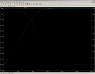
yes I added 100 Ohms as the series resistance in the "real" coil's parameters in spice. Attached is an expanded plot with the "real" coil having a series resistance of 1 Ohm (which is probably lower than possible for a 35H coil!)
I didn't like the idea of using a sallen key circuit and had been planning on trying something different, I was considering doing something with fdnr circuits, but on page three of this thread, D to the G posted a link to SY's acheron circuit, and this is the above post is the result of me reading enough to be able to understand the various bits and work out how to use LT spice to simulate it. Needless to say it has been a valuable learning experience!!
But until I actually build one and measure it, it is still speculation as to whether it will work...
Please don't hold your breath on that one, I tend to take a while!! but I have at least got the fets, and have roughly sorted them into ranges. I just have to get over the obsessing over other components and order the rest of the bits
Your welcome!!
Tony.
yes I added 100 Ohms as the series resistance in the "real" coil's parameters in spice. Attached is an expanded plot with the "real" coil having a series resistance of 1 Ohm (which is probably lower than possible for a 35H coil!)
The error actually starts quite a bit earlier than 8 Hz but at 10Hz it is only about 3 degrees... at 20Hz it looks like about 1 degree, so I guess effectively yes the error should be inaudibleAm I also correct in assuming that since this is a high pass 200Hz that the error that becomes measurable <8Hz will be completely inaudible?
I've read a fair bit about FDNR (this gyrator is like one) circuits in the past, and whilst some claim that they aren't in the signal path, others disagree, but I suspect that the effect will be lesser than if the signal was actually passing through the opamp.Is it also correct to assume that since the 134 is in the simulated inductor path, it has virtually no audible effect on the passband signal?
that's the plan!All we "hear" in the upper frequencies are the effect of two B1 follower stages.
I didn't like the idea of using a sallen key circuit and had been planning on trying something different, I was considering doing something with fdnr circuits, but on page three of this thread, D to the G posted a link to SY's acheron circuit, and this is the above post is the result of me reading enough to be able to understand the various bits and work out how to use LT spice to simulate it. Needless to say it has been a valuable learning experience!! But until I actually build one and measure it, it is still speculation as to whether it will work...
Please don't hold your breath on that one, I tend to take a while!! but I have at least got the fets, and have roughly sorted them into ranges. I just have to get over the obsessing over other components and order the rest of the bits
And finally,
thanks Winter.
Your welcome!!
Tony.
Attachments
Last edited:
wintermute,
Please post your opa134.sub and ?.sym files.
Thanks
Jim
Please post your opa134.sub and ?.sym files.
Thanks
Jim
Well I've done a lot of reading, brushed up on my algebra, played with ltspice a lot, and finally modeled something that I think might be workable. My planned crossover freq is 200Hz. (which seems to be right as the curve is down just over 6db at 200Hz).
Screen shot of the results of comparing an opa134 based gyrator to a passive circuit with a capacitor and real inductor. both curves are almost identical so I think the circuit is working as intended
Now I guess I just have to get round to actually building one!!! but at least this is some progress....
I've also attached the ltspice file of this model in case anyone is interested
Tony.
Hi Jim,
I've added opa134.sub and opa134.asy to the original zip file and re uploaded here (should have thought about that in the first place!), note that it is an asy file in ltspice but I suspect it is what you are after as It is under the sym directory.
The .sub was the pspice .mod file I downloaded from TI (hopefully accurate), the .asy was modified (simply by changing the SYMATTR Value, and SYMATTR Description lines) from the generic opamp2.asy file under sym/opamps
I'm a real newbie with ltspice so if I've done anything really dumb please let me know!!!
Thanks,
Tony.
Attachments
Last edited:
the filter should see near zero ohms feeding the input and near infinity ohms as load on the output.
A standard B1 gets close if you don't hang anything else on the B1's input/output.
Unfortunately B1 needs some resistance on it's output to be stable. some have reduced the 1k0 to 220r and find that works. Maybe a bit of experimentation on that to find what works. But whatever, the next R, of a low pass filter, must take the source resistance into account when assembling the active filter.
Andrew,
What is the imput impedance and output impedance of the standard B1 using 2sk170 JFETs?
Thanks,
Bill
the input impedance of a B1 is set by the input resistor to ground. If this is omitted the DC input resistance is very much higher.
There will be some capacitance at the jFET gate but this too will result in a very high input impedance at audio frequencies. The B1 with nothing attached to it's input quite effectively meets the infinite input impedance that filters require to see.
The output impedance is the sum of the Stage output impedance and the output resistor. The standard B1 uses 1k0, giving a total output impedance of ~1050ohms.
The 1k0 output resistor can be reduced. As in the DCB1 220r is used giving a total output impedance of ~270ohms.
This does not meet the zero ohm source impedance that filters require to see.
An active low pass filter starts with a resistor feeding the remainder of the circuit. All that is required is to measure the actual output impedance of the B1 and subtract this from the theoretical first filtering resistor, so that the filter sees a total R as the feed resistor.
Not as easy for the high pass which starts with a series capacitor as the first component of the filter.
very approximately.Thanks, Andrew. So I presume the jFET has an output impedance of 50R.
I think it varies significantly with Idss of the chosen jFETs.
Higher Idss should give lower output impedance.
Tony,
I had a look at your circuit in post #222. R7, the 100R resistor, may create excessive current load for the opamp at high frequencies. In SY's paper he suggested 5k. That is safe. I guess you may try as low as 2k, but I would worry if it is lower. But if you scale the values up your R12 may become too large. Even the value of 3M5 seems unusual in opamp circuits.
Look forward to hearing your findings and evaluation of the sound quality of the gyrator.
Regards,
Bill
Hi Bill,
Yes I was a bit worried about that as well, which is why I said until I've built it I won't know if it works However this is what Rod Elliot has to say about it
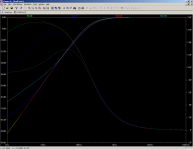
The red trace is an "ideal" inductor with series resistance of 0.1 ohms, which is effectively unobtainable for a 35H coil.
the green trace is with 100 ohms for R1
the blue trace is with 1K for R1
The turquoise trace is with 5k for R1
other values adjusted accordingly
changing the series resistance on the passive L in the simulation to match the value of R1 gives identical results to the active circuit.
So me being the performance tweaking type that I am I wanted to try and ring every last drop out of the circuit and decided to try for the 100Ohms..
the 1K R1 is very good with respect to the freq response tracking the ideal inductor (down to about 10Hz) but the phase is off quite a bit, so if I cook the opamp with 100R then 1K would probably be an ok compromise. The error introduced by the 5K I felt was unacceptable.
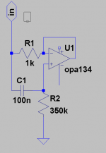
I also attached a pic of just the gyrator part of the circuit for anyone scratching their head saying what is R1
edit: The third image is the same as the first except with 2K for R1 on the turquoise trace.
Tony.
Yes I was a bit worried about that as well, which is why I said until I've built it I won't know if it works
However this is what Rod Elliot has to say about it So I decided that if Spice thought it would work, it was worth having a crack at. I've attached an image of the difference with differing values of R1.The simulated inductor cannot be made with high Q, since the value of R1 cannot be made low enough to allow a Q of more than about 10. This is due to the limitations of the opamp - a minimum value of 100 ohms is usually specified for R1, although lower values are sometimes used. This represents a series resistance (equivalent to wire resistance in a real inductor.
The red trace is an "ideal" inductor with series resistance of 0.1 ohms, which is effectively unobtainable for a 35H coil.
the green trace is with 100 ohms for R1
the blue trace is with 1K for R1
The turquoise trace is with 5k for R1
other values adjusted accordingly
changing the series resistance on the passive L in the simulation to match the value of R1 gives identical results to the active circuit.
So me being the performance tweaking type that I am I wanted to try and ring every last drop out of the circuit and decided to try for the 100Ohms..
the 1K R1 is very good with respect to the freq response tracking the ideal inductor (down to about 10Hz) but the phase is off quite a bit, so if I cook the opamp with 100R then 1K would probably be an ok compromise. The error introduced by the 5K I felt was unacceptable.
I also attached a pic of just the gyrator part of the circuit for anyone scratching their head saying what is R1
edit: The third image is the same as the first except with 2K for R1 on the turquoise trace.
Tony.
Attachments
Last edited:
ok I've measured the current flowing through R1 in spice. Not sure if I've done it correctly though because it is VERY low.... It does go up with increasing freq much more with the 100R R1 but the max current is around 1 milliamp at 1mHz and 9ma at 10Mhz, I certainly hope I don't have any 10Mhz and even if I did I think the opamp will handle 9mA
Doing an fft on it gives me a very different result of 560 Kilo Amps, so I'm going to assume that it wasn't an appropriate measurement I think I'll have to read up on what the fft is for!!
Tony.
Doing an fft on it gives me a very different result of 560 Kilo Amps, so I'm going to assume that it wasn't an appropriate measurement
I think I'll have to read up on what the fft is for!!Tony.
Attachments
Last edited:
Tony,
Surely you know what you are doing! I am only a skeptical and critical guy and am very conservative. Until lately, I have never been able to get the opamp rails not resonate - the inductive output of line level regulators due to limited open loop gain, the wire inductance and the input capacitance of opamps usally cause ringing, adding high Q film local bypass capacitors introduces a whole new set of problems. I could only solve those problems with the help of an oscillioscope. Opamps do not have high PSSR at high frequencies. So I have seen a lot ripples from 2MHz to 25Mhz in reality. Although completely out of the audio band, they affect the sound significantly.
Regards,
Bill
Last edited:
Bad assumption Bill, I truly do not!!! I'm learning as I go, so as with a lot of things I may well learn the hard way
You have demonstrated with your post that you already know a lot more than me about the hazards of using opamps. I'd be interested to know what opamps you had trouble with. I've Had problems with ne5534's which are unstable without compensation caps. From what I have read the higher the bandwidth of the opamp, the more liklely you will have problems with it, and the more important the layout is.
I chose the opa134's because they had better noise specs than the lowly tl072 and slightly higher bandwidth, but they are still not that high at 8Mhz. I don't have a scope, so if I do get problems with oscillation I'll have a hard time tracking it down.
I was basically going to follow the guidelines in the datasheet for bypassing (I didn't worry about it on the spice model) but note that they are not very picky about it for these opamps (only recommend a 10nf Ceramic)... One of the LT chips I looked at had very stringent requirements listed including multiple caps and the distances they needed to be from the pins (small value close as possible, and then 10uf electros at least 10mm away or something like that) as well as requirements for dual layer boards to minimise capacitive effects between the pads and the other side of the board...
Hopefully the rather lowly opa134 should keep me out of trouble in that respect!
I'm also going to be designing my own powersupply. Nothing fancy and some will cringe that I'm going to use LT317A's (for both +ve and -ve rails)... This B1 xover is going to be different, it will probably end up somewhere between Salas's DC B1 and the original. But how long before I've built it I don't know yet... Hopefully no where near as long as my MTM's!! If I can do it in double the time I took for my 2p2 Gainclone that would be great (that was two weeks) but I had the advantage then I wasn't working, so I suspect it will be a tad longer...
Oh and I'm going to be building on verro board, not a pcb, just to add an extra element of risk Wish me luck!!!
cheers,
Tony.
edit: I didn't like the idea of using ceramic's but after your comment about problems with film caps I decided to do a google search for ceramic vs film for opamp bypassing, and the first link I clicked on was this one http://tangentsoft.net/audio/hs-opamp.html which seems to be very appropriate to the conversation.. I'm going to read it and digest what it has to say!!
You have demonstrated with your post that you already know a lot more than me about the hazards of using opamps. I'd be interested to know what opamps you had trouble with. I've Had problems with ne5534's which are unstable without compensation caps. From what I have read the higher the bandwidth of the opamp, the more liklely you will have problems with it, and the more important the layout is.
I chose the opa134's because they had better noise specs than the lowly tl072 and slightly higher bandwidth, but they are still not that high at 8Mhz. I don't have a scope, so if I do get problems with oscillation I'll have a hard time tracking it down.
I was basically going to follow the guidelines in the datasheet for bypassing (I didn't worry about it on the spice model) but note that they are not very picky about it for these opamps (only recommend a 10nf Ceramic)... One of the LT chips I looked at had very stringent requirements listed including multiple caps and the distances they needed to be from the pins (small value close as possible, and then 10uf electros at least 10mm away or something like that) as well as requirements for dual layer boards to minimise capacitive effects between the pads and the other side of the board...
Hopefully the rather lowly opa134 should keep me out of trouble in that respect!
I'm also going to be designing my own powersupply. Nothing fancy and some will cringe that I'm going to use LT317A's (for both +ve and -ve rails)... This B1 xover is going to be different, it will probably end up somewhere between Salas's DC B1 and the original. But how long before I've built it I don't know yet... Hopefully no where near as long as my MTM's!! If I can do it in double the time I took for my 2p2 Gainclone that would be great (that was two weeks) but I had the advantage then I wasn't working, so I suspect it will be a tad longer...
Oh and I'm going to be building on verro board, not a pcb, just to add an extra element of risk
Wish me luck!!! cheers,
Tony.
edit: I didn't like the idea of using ceramic's but after your comment about problems with film caps I decided to do a google search for ceramic vs film for opamp bypassing, and the first link I clicked on was this one http://tangentsoft.net/audio/hs-opamp.html which seems to be very appropriate to the conversation.. I'm going to read it and digest what it has to say!!
Last edited:
I am donating my 2 cents here hopefully to save some time for some.
The idea of having jFET buffers for XO must be based on the almost universal belief that simple jFETs circuits sound better than opamps, otherwise there is no point doing so, because opamps are far more flexible to work with. In addition to working as a buffer it can also work with gain, feedback, etc, with overload protection, etc.
The jFET idea was very appealing to me, as I was about to build my already designed XO filters for my active 4 way speakers. I thought at least the tweeter branch should use jFETs.
Before I made a commitment, I first built a DCB1 buffer. Subjectively, the buffer sounded in the similar level of performance as the opa627 with different flavour, but possibly not better or worse. If I have to magnify the differences, then I have to say that the opa627 sounded like a good solid state amp, while the jFETs sounded like a upper midrange tube amp. They have different distortion profiles. The jFETs may appear to be slightly more musical, while the opa627 sounds more open, dynamic with darker background and possibly more accuracy.
So I have decided to use the opa627 for my XO filters for the tweeter and midrange, and use lm4562 for the woofer and subwoofer.
What I have found with opamps is that they do require a very good PSU in order to sound right, regardless of their claimed highish PSSR. It is extremely easy to have resonance in the rails if you follow the manufacturers' datasheets and put some 0.1uF ceramic or film cap at the pins of the opamp supply. I have found that the regulator output inductance, the wire inductance, the opamp input capacitance and the local 0.1uF bypass capacitance form a LCR resonance circuit. No wonder I never found opamps to sound good before. Fortunately, I have lately found the shunt regulators designed by Salas and Ikoflexer and have implemented them with opamps with very clean rails. Now the opamps sound good.
So before you put in extra efforts designing your jFET XO, you may build a jFET buffer and compare to an opamp on a top-notch PSU regulator first.
Last edited:
What about implementing a delayed start like in DCB1? This way we can get away of DC problems when turning on/off.brilliant!
It looks so simple. Unity gain and equal value R & C automatically gives Q=0.5 for the L-R function and makes it so simple to match components.
Be careful to check for DC at the outputs. Both at switch on and as the devices warm up. The low pass is particularly susceptible since it is completely DC coupled all the way through.
And for the 25k volume pot for each of the filtered stages, it will be feasible to implement a Lightspeed attenuator to get the best performance. That way, it wouldn't matter pot quality
I would go with a DCB1 implementation, both shunts regulators and the buffer stage. We could use a regulator for each stage. That would be easy with the already designed and tested board from Salas and CRT.
We could use a board for each inter-stage, let's say:
General volume -> DCB1board -> Filters -> Indiv. volume control -> DCB1board
What are your thoughts regarding this approach?
The idea of having jFET buffers for XO must be based on the almost universal belief that simple jFETs circuits sound better than opamps, otherwise there is no point doing so, because opamps are far more flexible to work with. In addition to working as a buffer it can also work with gain, feedback, etc, with overload protection, etc.
The jFET idea was very appealing to me, as I was about to build my already designed XO filters for my active 4 way speakers. I thought at least the tweeter branch should use jFETs.
Before I made a commitment, I first built a DCB1 buffer. Subjectively, the buffer sounded in the similar level of performance as the opa627 with different flavour, but possibly not better or worse. If I have to magnify the differences, then I have to say that the opa627 sounded like a good solid state amp, while the jFETs sounded like a upper midrange tube amp. They have different distortion profiles. The jFETs may appear to be slightly more musical, while the opa627 sounds more open, dynamic with darker background and possibly more accuracy.
So I have decided to use the opa627 for my XO filters for the tweeter and midrange, and use lm4562 for the woofer and subwoofer.
What I have found with opamps is that they do require a very good PSU in order to sound right, regardless of their claimed highish PSSR. It is extremely easy to have resonance in the rails if you follow the manufacturers' datasheets and put some 0.1uF ceramic or film cap at the pins of the opamp supply. I have found that the regulator output inductance, the wire inductance, the opamp input capacitance and the local 0.1uF bypass capacitance form a LCR resonance circuit. No wonder I never found opamps to sound good before. Fortunately, I have lately found the shunt regulators designed by Salas and Ikoflexer and have implemented them with opamps with very clean rails. Now the opamps sound good.
So before you put in extra efforts designing your jFET XO, you may build a jFET buffer and compare to an opamp on a top-notch PSU regulator first.
Hifi,
By DCB1 did you mean a DC coupled B1?
My experience was quite different. My amp had an onboard opamp based buffer/low pass filter. For this opamp I had tried a variety of chips including 627 and 4562. My first trial was a capacitor coupled B1 which replaced the opamp. B1 ran circles around the opamp. It sounded significantly better than the 627, not just slight differences in characteristics. From a supply stand point both the opamp and the B1 were driven by a generic 78xx/79xx regulators.
I would definitely would love to hear more people trying this experiment, you suggest.
Hi,
how many sk170 can you buy for the cost of one 627? How much fun do you get from building e.g. this XO with those little critters?
And at least in my frame of reference the solution from this thread sounds better than the OP based solutions I tried, I did not try it with 627s but with other well regarded items. But I am shure you can make a OP solution sound better than my one, just a matter of effort you can and will afford.
But let's stop this discussion here, there might be no end.
Regards
Flo
- Status
- This old topic is closed. If you want to reopen this topic, contact a moderator using the "Report Post" button.
- Home
- Amplifiers
- Pass Labs
- B1 Active Crossover