Will do.
What AWG sizes are typically used in an 7'' midbass? 31 AWG?
How about a 7'' fullrange?
I've already put in a small order for 3 AWG sizes, 31, 33 and 35. 100m, 50m and 25m length respectively. I've modelled a 1.5mm gap that will suit up to 4 layers of 31 AWG on a 5mm coil.
I used this coil calculator.
"What AWG sizes are typically used in an 7'' midbass? 31 AWG?
How about a 7'' fullrange? "
It depends on the design. If you just want to make a sample it doesn't really matter.
Cone weight/spider compliance/desired qts etc.. matter otherwise
31awg is ~0.255 *4 = 1.02 + former+clearance ~ = 1.75mm gap is more viable
you can use femm to calculate DC inductance but it's near pointless. femm is unable to simulate AC fields with permanent magnetic fields (as most of the FEAs), and if you're going to use that shorting ring to reduce inductance you don't just have to increase gap width but you also cannot rely on femm AFAIK.
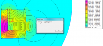
"how do I calculate the flux density at a point in the gap"
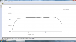
Just place two points above and below the gap and draw a line ('red line') (contours) between the two points.
then plot B.n
Also you can read about TS params if you want a specific design with specific resonance etc.. (i have one somewhere i can dig it up to you if you want it but the net is full of ts calculators)
you don't need large xmax anyway, for 7" midrange above 100hz 2.5mm is enough to hit 100dB for one unit.
How about a 7'' fullrange? "
It depends on the design. If you just want to make a sample it doesn't really matter.
Cone weight/spider compliance/desired qts etc.. matter otherwise
31awg is ~0.255 *4 = 1.02 + former+clearance ~ = 1.75mm gap is more viable
you can use femm to calculate DC inductance but it's near pointless. femm is unable to simulate AC fields with permanent magnetic fields (as most of the FEAs), and if you're going to use that shorting ring to reduce inductance you don't just have to increase gap width but you also cannot rely on femm AFAIK.
"how do I calculate the flux density at a point in the gap"
Just place two points above and below the gap and draw a line ('red line') (contours) between the two points.
then plot B.n
Also you can read about TS params if you want a specific design with specific resonance etc.. (i have one somewhere i can dig it up to you if you want it but the net is full of ts calculators)
you don't need large xmax anyway, for 7" midrange above 100hz 2.5mm is enough to hit 100dB for one unit.
there was a thread where some of the manufacturers alleged that the system must be magnetized after assembling because it won't have as much flux density than the other way.. (in opposite to the other half of the manufacturers..)
for me this sounds nonsense, btw.. he will have to build a magnetizing machine if he wants to ..
here is one: http://oersted.com/magnetizing.PDF
for me this sounds nonsense, btw.. he will have to build a magnetizing machine if he wants to ..
here is one: http://oersted.com/magnetizing.PDF
Last edited:
Have you looked at using the single 50mm magnet?
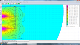
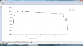
Results not good. 0.32T through 2mm gap. The ring neo does 0.545T through 2mm.
Attachments
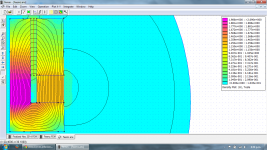
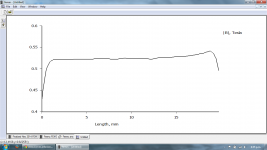
This simulation has a huge gap of 4mm and 15mm height. Flux is 0.7T. Provisions for 2X 1mm copper rings in the gap with plenty of clearance for the coil/former/tolerances/. Very flat BL. Theoretical X-Max is 5mm but the coil can extend another 5mm without much BL fluctuations.
Tried more simulations with the huge single neo but it was a complete failure. Very poor flux efficiency at the risk of demagnetizing the neo due to close proximity to the voice coil.
Tried more simulations with the huge single neo but it was a complete failure. Very poor flux efficiency at the risk of demagnetizing the neo due to close proximity to the voice coil.
Attachments
For large x-max you may have to punch holes in the cone (or anything else) to prevent air-flow noises (air trapped) beneath the dust cap.
http://www.audioholics.com/loudspea...rivers/copy_of_diagram_polk.jpg/image_preview
http://www.audioholics.com/loudspea...rivers/copy_of_diagram_polk.jpg/image_preview
Last edited:
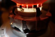
I've assembled the motor and made a 9.5'' paper cone with fiberglass as a surface layer. I'm surprised at the superb treble extension, all the way to 12Khz, highly audible with test tones. No measurement tools as of yet. No dustcap attached.
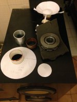
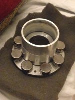
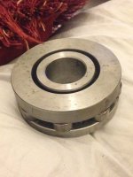
Assembly was very easy. I had an aluminium spacer machined to fit in the gap via a sliding fit. With the spacer in place, I epoxied the neo magnets to the pole surface. The neo magnets naturally repel each other when they're side by side so they naturally set up an even spacing around the pole piece. They had a tendency to drift toward and compress the alu spacer, so I used a 0.2mm thick plastic strip, jammed between the magnets and the alu spacer. Once the glue has dried, I put more glue on the top surface. The top pole piece was placed over the alu spacer. While holding chopsticks, Dad and me slowly lowered the angle of the sticks. We adjusted pressure to prevent slamming of the pieces, until just a few mm from the surface, the magnetic attraction was too strong and the 2 pieces clicked together delightfully! Once everything has dried well, I removed the alu spacer and press fit the copper ring in.
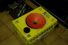
A cardboard box was placed over the speaker (I made a cutout for the cone). There is no surround, and I detect a 1.5Khz strong peak. High Q type.
Spider is made of 6 namecard strips, bent around a screwdriver, superglued to the cone. There is no bass at all due to severe air leaks, but the midrange is very sensitive and loud. When listening very close to the cone, I hear a full and rich sounding bass, it just disappears as I move away!
I have no idea what the T/S specs are!!
Cone : 9.5inch diameter, Fiberglass+paper 20 grams. I used paper from a cake box. It's around 0.4mm thick and feels like it's been plasticized.
Former : Nomex 0.1mm thick 30mm high, < 1 gram, glued with Araldite epoxy
Coil : 2'' AWG 34, 0.18mm, 7meters, 4mm tall, dual layer, hand wound, 3 grams weight.
There is a 1mm thick 25mm tall 2'' copper shorting ring around the pole piece, I think it is extending the high freq tremendously. 5mm of copper overhang around the 15mm tall pole piece on each side.
The gap is 4mm wide, I have not been able to get the second copper ring to fit in the gap. I'm not sure if it's needed or not.
Next up is the basket design and proper soft parts. I will follow Dynavox basket style, using 3 concentric rings as the basket.
This has been a very fun project!!
Assembly was very easy. I had an aluminium spacer machined to fit in the gap via a sliding fit. With the spacer in place, I epoxied the neo magnets to the pole surface. The neo magnets naturally repel each other when they're side by side so they naturally set up an even spacing around the pole piece. They had a tendency to drift toward and compress the alu spacer, so I used a 0.2mm thick plastic strip, jammed between the magnets and the alu spacer. Once the glue has dried, I put more glue on the top surface. The top pole piece was placed over the alu spacer. While holding chopsticks, Dad and me slowly lowered the angle of the sticks. We adjusted pressure to prevent slamming of the pieces, until just a few mm from the surface, the magnetic attraction was too strong and the 2 pieces clicked together delightfully! Once everything has dried well, I removed the alu spacer and press fit the copper ring in.
A cardboard box was placed over the speaker (I made a cutout for the cone). There is no surround, and I detect a 1.5Khz strong peak. High Q type.
Spider is made of 6 namecard strips, bent around a screwdriver, superglued to the cone. There is no bass at all due to severe air leaks, but the midrange is very sensitive and loud. When listening very close to the cone, I hear a full and rich sounding bass, it just disappears as I move away!
I have no idea what the T/S specs are!!
Cone : 9.5inch diameter, Fiberglass+paper 20 grams. I used paper from a cake box. It's around 0.4mm thick and feels like it's been plasticized.
Former : Nomex 0.1mm thick 30mm high, < 1 gram, glued with Araldite epoxy
Coil : 2'' AWG 34, 0.18mm, 7meters, 4mm tall, dual layer, hand wound, 3 grams weight.
There is a 1mm thick 25mm tall 2'' copper shorting ring around the pole piece, I think it is extending the high freq tremendously. 5mm of copper overhang around the 15mm tall pole piece on each side.
The gap is 4mm wide, I have not been able to get the second copper ring to fit in the gap. I'm not sure if it's needed or not.
Next up is the basket design and proper soft parts. I will follow Dynavox basket style, using 3 concentric rings as the basket.
This has been a very fun project!!
Attachments
Absolutely great work Dinesh!
It would be better to make the cone without folding, I mean, you cannot make a curvilinear cone this way")
Anyway it's great!
Only some surrounds and baskets are needed!
You can go for DIY cloth surrounds and spiders as well, use a large surround!
That A4 box rules..
It would be better to make the cone without folding, I mean, you cannot make a curvilinear cone this way
Anyway it's great!
Only some surrounds and baskets are needed!
You can go for DIY cloth surrounds and spiders as well, use a large surround!
That A4 box rules..
Absolutely great work Dinesh!
It would be better to make the cone without folding, I mean, you cannot make a curvilinear cone this way
Anyway it's great!
Only some surrounds and baskets are needed!
You can go for DIY cloth surrounds and spiders as well, use a large surround!
That A4 box rules..
Thanks so much! Exactly, the cone is just a straight cone now, about 30 degrees. Will need a mould of sorts. Plenty of proper parts to build, and I will try the cloth suspension and surround. I never knew a cardboard box could sound so good..probably because of no mechanical coupling to the box!
Inductance affects the highs significantly..
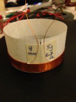
I wound a new VC with almost double the length and height, using thicker 0.22mm wire (AWG 32). I removed the old VC with a razor and glued the new one in. Huge increase in sensitivity and loudness but I've lost some of the highs as well. Sound is more powerful but not as open and "fast" as before.
Old coil : AWG 34, 0.18mm, 7m, 4mm tall, dual layer, hand wound, 3 grams
~6.5 Ohms.
New coil : AWG 32, 0.22mm, 12.5m, 8mm, dual layer, hand wound, 5 grams.
~6.8 Ohms
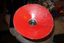
Here is the new coil :
I wound a new VC with almost double the length and height, using thicker 0.22mm wire (AWG 32). I removed the old VC with a razor and glued the new one in. Huge increase in sensitivity and loudness but I've lost some of the highs as well. Sound is more powerful but not as open and "fast" as before.
Old coil : AWG 34, 0.18mm, 7m, 4mm tall, dual layer, hand wound, 3 grams
~6.5 Ohms.
New coil : AWG 32, 0.22mm, 12.5m, 8mm, dual layer, hand wound, 5 grams.
~6.8 Ohms
Here is the new coil :
Attachments
5.5m extra length and 0.04mm increase in diameter and it's only 2grams heavier?IOld coil : AWG 34, 0.18mm, 7m, 4mm tall, dual layer, hand wound, 3 grams
~6.5 Ohms.
New coil : AWG 32, 0.22mm, 12.5m, 8mm, dual layer, hand wound, 5 grams.
~6.8 Ohms
............
The wire volume has gone up by 2.67times.
2.67times 3grams = 8grams. An increase of 5grams.
- Status
- This old topic is closed. If you want to reopen this topic, contact a moderator using the "Report Post" button.
- Home
- Design & Build
- Parts
- Axial or Diametrical neo magnets for homemade speaker?