cool
")
one problem may be that its difficult to make a very accurate magnet gap
Tinitus, that looks simple and efficient. What speaker motor simulation software are you using?
sretie answered that very well, in his own way
Thanks for the ideas.
I hope you will have fun trying

btw, my 'poor' suggestion is an effort to show how it might be done using ordinany plumming tube, or other 'standard material', with a minimum of work needed

wish you a merry christmas too

sretie answered that very well, in his own way
I hope you will have fun trying
Merry Christmas to you too!
Sreten is very selfless in his help to the community.
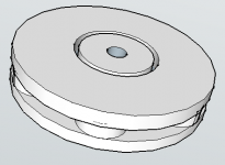
A more conventional neo design using 0.75'' X 0.25'' neo magnets :
- OD of motor 80mm
- OD 30mm voice coil
- 2mm air gap
-5mm thick pole pieces
The height of the motor is only around 15mm which is hopelessly tiny.
Ventilation would be excellent as there are gaps around the magnets to help with air flow.
1. What should the maximum thickness of the pole pieces be to produce maximum flux in the air gap, yet be fully saturated?
2. Should the neo magnets be placed as closely as possible to the circumference of the pole piece?
Just had a look at FINEmotor design software by loudsoft.com, costs around 2900 Euros! Would be great if I can use a free software for these basic simulations. There is a certain thrill in designing transducers...a big change from always designing enclosures/crossover for loudspeakers.
This will be very fun.
Merry Christmas to all!

Attachments
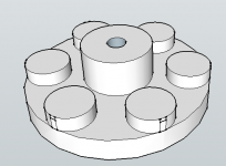
Underhung motor with full copper rings/disc.
Some design features :
- 8X (3/4'' X 3/8'') N52 Neo disc magnets
- 20mm pole piece (gap height)
- 2mm gap
- 5mm coil winding height
- X-Max of ((20-5)/2) = 7.5mm one way
- 2 inch voice coil wound on 0.1mm thick Kapton former
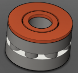
- 0.5mm thick copper rings inside both pole pieces (3rd pic)
- 5mm thick copper on surfaces
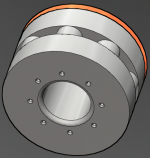
- Ventilation through magnet gaps
- Ventilation through 8X 1mm holes through gap (1mm fillet)
- Ventilated/Slit Dustcaps
- 35mm vented pole piece with 5mm fillet
- 150 watt continuous power handling
Newbie designer here , please let me know if there is something seriously wrong with the design. Appreciate it if anyone can simulate this design.
Some design features :
- 8X (3/4'' X 3/8'') N52 Neo disc magnets
- 20mm pole piece (gap height)
- 2mm gap
- 5mm coil winding height
- X-Max of ((20-5)/2) = 7.5mm one way
- 2 inch voice coil wound on 0.1mm thick Kapton former
- 0.5mm thick copper rings inside both pole pieces (3rd pic)
- 5mm thick copper on surfaces
- Ventilation through magnet gaps
- Ventilation through 8X 1mm holes through gap (1mm fillet)
- Ventilated/Slit Dustcaps
- 35mm vented pole piece with 5mm fillet
- 150 watt continuous power handling
Newbie designer here , please let me know if there is something seriously wrong with the design. Appreciate it if anyone can simulate this design.
Attachments


When one uses ferrite magnet the backplate and the front plate MUST be smaller than the diameter of the ferrite.
I don't know how much smaller.
The reason for this is to prevent the flux short circuiting the magnetic gap. Instead of the flux traveling around the motor circuit it jumps directly from backplate to front plate across the "air" just outside magnet thickness.
Does this "rule" for ferrite also apply to other thin magnets?
If the answer is yes, then the posts 24 & 25 will enable the flux short circuit.
Who knows?
You are probably right.
Magnetic flux lines don't know or care about magnet alloy formulation, only about the magnetic resistence they find in their path, so, yes, the design shown will probably waste a lot of magnetic energy.
FWIW the "unwritten rule" is making iron disks roughly 10% smaller than ring magnet diameter.
I make my own speakers, and my most popular ones use a 96mm disk for a 102/105 mm magnet, 118mm disks for 126 mm magnets and 130/135mm ones for 147 mm magnets.
Best would be make them almost same diameter as magnets, but with lathe turned edges bevelled to a 45 deg angle, but you won't see many speakers made that way, since it adds to the cost.
When one uses ferrite magnet the backplate and the front plate MUST be smaller than the diameter of the ferrite.
I don't know how much smaller.
Who knows?
Hi,
No. That is simply not true. It is true its near pointless making
them bigger than the magnets, and obviously if oversized the
extra doesn't do anything other than create more leakage flux.
As you have surmised, and nearly all ferrite magnet systems
follow this path, slightly undersized is optimum, but it is not
a "MUST", it is just the most sensible way of doing it.
A few ferrite drivers go right up to the magnet edges.
Its not a problem, probably just a standard parts issue.
rgds, sreten.
When one uses ferrite magnet the backplate and the front plate MUST be smaller than the diameter of the ferrite.
I don't know how much smaller.
The reason for this is to prevent the flux short circuiting the magnetic gap. Instead of the flux traveling around the motor circuit it jumps directly from backplate to front plate across the "air" just outside magnet thickness.
Does this "rule" for ferrite also apply to other thin magnets?
If the answer is yes, then the posts 24 & 25 will enable the flux short circuit.
Who knows?
Hi AndrewT, flux shorting could happen, but in this design, my pole pieces are 20mm thick. They wouldn't be fully saturated. This serves to concentrate most of the flux to the gap. A more realistic gap height would be between 13 to 15mm. I don't have any software to test this but once I build the motor, I will be doing distortion tests to see how it compares with a Scanspeak/AudioTech motor.
This Neo design is borrowed from the Scanspeak AirCirc motor and also Focal's Power Flower motor. In Focal's case they are using ferrite magnets.
My previous post is missing............. but in this design, my pole pieces are 20mm thick. They wouldn't be fully saturated. This serves to concentrate most of the flux to the gap.............
I will wait a bit longer to see if it needs editing.
I don't know if saturation of the poles pieces affects the tendency to short circuit.
If is as far as I have read that the short route from north pole to south pole that creates the shorting of the flux.
This may be limited to all very thin magnets, or it might be limited to only ferrite.
You are probably right.
Magnetic flux lines don't know or care about magnet alloy formulation, only about the magnetic resistence they find in their path, so, yes, the design shown will probably waste a lot of magnetic energy.
FWIW the "unwritten rule" is making iron disks roughly 10% smaller than ring magnet diameter.
I make my own speakers, and my most popular ones use a 96mm disk for a 102/105 mm magnet, 118mm disks for 126 mm magnets and 130/135mm ones for 147 mm magnets.
Best would be make them almost same diameter as magnets, but with lathe turned edges bevelled to a 45 deg angle, but you won't see many speakers made that way, since it adds to the cost.
Hi JMFahey, thanks for your thoughts. The Scanspeak 18W8531 motor has both pole pieces offset about 5mm from the magnets. 100mm OD pole pieces, 110mm OD magnet. I am hoping to get a powerful magnetic field which can be used to try out a few cone sizes, from 4'' to even 12''.
and the edit becomes.Once again, you disagree.
I stand by my must assertion.
The pole pieces (back plate and front plate) MUST be smaller than the ferrite magnet to avoid the short circuiting.
I don't know how much smaller and how the thinness of the magnetic material affects the underlap (opposite to overlap).
1. What should the maximum thickness of the pole pieces be
to produce maximum flux in the air gap, yet be fully saturated?
2. Should the neo magnets be placed as closely as
possible to the circumference of the pole piece?
Hi,
1) Is a very circular design process. You want the top plate to
saturate only very near the gap. That will be a defined level of flux
for the top plate material and will limit the gap flux. Hence the gap
width and depth would be designed for a slightly higher flux,
assuming a given field strength and flux capability of the
magnet(s) used. For a given magnet size more strength =
less flux capability so a careful balance creates optimum.
Also note some cheaper drivers don't try to saturate the poles.
2) I'd say further in rather than right on the edge,
but its hard to say where exactly is correct.
For ferrite to produce the right level of strength and flux
the magnet length is short and its area large. AlNiCo on
the other hand, to do the same job, the magnet can
be the centre pole piece, they are longer with much
less area to do the same job.
Neo is after my time of really look at the issues,
but I gather comparatively you have lots of flux
available for a given strength, hence short coil
/ long gap design is more prevalent, but not
always the case, like Seas Excel drivers.
rgds, sreten.
there probably will be a small loss at poleplate edge
might be the reason for making the poleplate edge thin, or rounded
Jacques Mahul(Focal) designed woofers with multiple small cylindrical magnets many years ago
actually I think he did this before the neo magnets entered
and there are some very exstreme Japanese designs, ofcourse
might be the reason for making the poleplate edge thin, or rounded
Jacques Mahul(Focal) designed woofers with multiple small cylindrical magnets many years ago
actually I think he did this before the neo magnets entered
and there are some very exstreme Japanese designs, ofcourse
Once again, you disagree. I stand by my must assertion.
The pole pieces (back plate and front plate) MUST be smaller
than the ferrite magnet to avoid the short circuiting.
Hi,
There is no short circuiting and your assertion is incorrect.
A "short circuit" would be extending the plates and joining
them together with pole material, clearly wrong. Just
extending the plates outside the magnet is pointless
but it is not catastrophic, it is nowhere near a "short
circuit" unless the plates are a utterly humungous size.
The magnetic path introduced is far higher "impedance"
than the voice coil gap and no way represents a "short".
There is nothing true about the assertion the pole pieces
MUST be smaller than the ferrite magnet. They can easily
be the same size, or pointlessly bigger with little effect.
It is not true that consequently the pole sizes are critical.
The are gernerally inset a bit, insetting the pole pieces beyond
about 1/4 of the ferrite magnets thickness is not common.
The closer the pole pieces get to the edge of the ferrite, the
less of the magnet is wasted, as they don't do sideways
very well, most are just somewhere near, not critical.
rgds, sreten.
Would be an interesting discussion about it magnetics design. (click the image)
Last edited:
Agree that the *word* "short circuit" was a poor choice.
That does not detract from the fact that **a lot** of magnetic flux is lost "outside".
Magnetic flux lines try to go from North to South (it's a convention, ok?, don't waste time nitpicking on this minor point) by multiple paths; it's the speaker designer's job that a lot of them do that through the VC gap doing useful work, anything else is waste.
FWIW the rule of thumb is that in *good* designs just 50% (best case) magnetic energy goes through the gap, go figure, so from the start we are wasting 50% .... or more.
I would not call that "a little effect", at all.
Let's analyze magnetic flux through the gap vs magnetic flux "outside"
Think about it 10 seconds and you'll "see":
1) compare magnetic flux (analogous to "current")along a certain path a result of magnetic "strength" (analogous to "voltage" ) and magnetic resistance (analogous to ohmic resistance)
2) "current" will flow depending on path resistance, which in due turn will depend on path "resistivity" , length and surface.
Hope so far the analogy is clear.
3) now to refresh some concepts:
a) "battery voltage" is the same in both paths, since the magnet is the same and we assume homogeneous top and bottom magnetization.
Which is true in a speaker magnet; (not so in magnets for motors, generators, etc. , but it's not the case here).
b) the polepiece is considered a magnetic short (or at least a very low magnetic resistance path), same with iron plates, both North and South.
(that's why I can consider flux density uniform at the top and bottom surfaces)
4) so we now can clearly see 2 main paths for magnetic lines to travel from North to South (from top plate to bottom plate):
a) through the VC gap, jumping through thin air.
b) "outside" , jumping straight from top plate to bottom plate, through thin air.
THAT OUTSIDE PATH IS ALSO A GAP.
And will "suck" its share of magnetic lines of force.
5) so how much will go "inside", how much will be lost "outside"?
Well, this seemingly complex problem ends up being not that tough to solve, at all.
No fancy/expensive software needed .... although FEMM will probably confirm this in an interesting graphic way.
And why do I say it's "easy"?
because it ends up being a simple *geometry* problem .... because, you'll see:
"voltage" is the same for both paths ..... because magnet is the same
"resistivity" is the same , because in both the path goes through the same medium: air.
Which has huge but defined "magnetic resistivity" .
So back to both paths: magnetic flux ("current") will now depend on air path resistance, all other factors even out.
6) I'll use some typical values, pulled from one of my own speakers:
VC gap: 32 mm diameter, 6 mm height (plate thickness), gap width 1 mm (center pole piece 32 mm diameter; top plate hole 34 mm)
"outside gap" : 100 mm diameter magnet, 6mm height (obviously, plates are uniform thickness), equivalent "gap width" = distance from top to bottom plate = magnet thickness = 15 mm.
So let's compare both "path resistances", to see how magnet line forces will split
I repeat: since all other physical parameters are the same, comparing just geometry will be enough.
as in:
a) longer path= higher resistance
b) wider path (more surface)= lower resistance (analogous to having a poorer resistivity conductor, but of higher diameter)
7) so now let's pull the calculator and do some easy number crunching:
a) outside path is longer , 15mm vs. 1 mm, maybe that's why Sreten thinks it's no problem .... but he's seeing just *one* parameter .
So far flux lost outside seems to be 1/15 of the useful flux.
b) outside path is wider, to the tune of 100 mm diameter vs 32 mm diameter, a 3:1 ratio, which multiplies losses by 3
So now loss is 3/15 = 1/5 = 20% .
Well, 20% loss *starts* to be felt.
But now we have another problem to consider:
VC gap is *small* (we just saw that) and flux densities approach (or reach) saturation levels ... which in a simple language means iron starts losing a lot of its permeability , meaning it no longer is a very low loss magnetic path .... in fact as it approaches saturation it starts behaving like .... air (ugh) , so that 1 mm gap starts behaving like if it were 1.5 mm or even 2 mm ..... and whatever it loses will go through "the other" path, meaning the lossy "outside"
Start adding these real world losses, and it's easier to understand why no more than 50% of available magnetic energy reaches the useful VC gap.
In poor cheap Chinese speakers, with huge magnets but also with huge gaps (which ease manufacturing) loss is as bad as 75% (I've measured it).
Back to the original discussion: what if we use oversized plates?
Well, it's *easy* to see that losses will increase a lot, even with slightly oversized plates.
Using my measurements, if we extend those plates just 6 mm (which according to sreten should be "nothing") , we are doubling outside gap surface, thus halving its resistance, and doubling loss.
Not what I would call inconsequential or meaningless.
That's why *everybody* uses roughly 10% smaller plates.
And it's easy to say why: again using my real world measurements, "retracting" plates by 6 mm doubles the outside gap path and halves loss ..... how's that ?
By the way, even sreten's picture shows that
Hi,
You could use radially (not diametrically) magnetized ndfeb segments actually (the AURA NS6-255-8A is a good ex.)
but just start with axial
"what type of magnet would be suitable to achieve the strongest surface magnetic field?"
ndfeb high grade, or field coil also you will have to use low carbon steel (1010, 1016)
"the voice coil should be moving perpendicularly to the magnetic field of the permanent magnet. Doesn't this suggest a diametrical magnet?"
current is flowing thru the voice coil, it creates small circular magnetic fields around the wire (just google up "inductor magnetic field")
the magnetic flux of the gap which couples to the field of the voice coil is B. the force is F = IL x B sinO (sinO is 1 since B in the gap is annular) L is the length of the wire, and I is the electric current.
the exerted force is perpendicular to both B and and I (also depends on the direction of the flux) so the coil moves up or down.
axial (if used with steel) or radial magnets are needed, any kind of shape is useful
Are you familiar with femm? i suggest you to play with it for a while (magnet2d/3d is also useful), it'll give you
some idea how to start.. saturation depends on the material. Finemotor is also great.
"150 watt continuous power handling"
this is very hard to predict.. depends on VC diameter, cooling, wire gauge (enclosure type?) etc..
those magnets are very dangerous.. i wouldn't try to assemble them in a magnetized state.. let me know if you have been successful
"I don't have any software to test this" just test it with femm or magnet2d/3d (free demo available AFAIK)
"1) Is a very circular design process. You want the top plate to
saturate only very near the gap"
#25 yeah, most certainly true
#37
definitely a design!!
flux lines flow in the lower magnetic resistance (remanence) as in electronics, however stray flux can be used to add up to the useful BL
Good drawings, anyway!
rgds, Akos
You could use radially (not diametrically) magnetized ndfeb segments actually (the AURA NS6-255-8A is a good ex.)
but just start with axial
"what type of magnet would be suitable to achieve the strongest surface magnetic field?"
ndfeb high grade, or field coil
also you will have to use low carbon steel (1010, 1016)"the voice coil should be moving perpendicularly to the magnetic field of the permanent magnet. Doesn't this suggest a diametrical magnet?"
current is flowing thru the voice coil, it creates small circular magnetic fields around the wire (just google up "inductor magnetic field")
the magnetic flux of the gap which couples to the field of the voice coil is B. the force is F = IL x B sinO (sinO is 1 since B in the gap is annular) L is the length of the wire, and I is the electric current.
the exerted force is perpendicular to both B and and I (also depends on the direction of the flux) so the coil moves up or down.
axial (if used with steel) or radial magnets are needed, any kind of shape is useful
Are you familiar with femm? i suggest you to play with it for a while (magnet2d/3d is also useful), it'll give you
some idea how to start.. saturation depends on the material. Finemotor is also great.
"150 watt continuous power handling"
this is very hard to predict.. depends on VC diameter, cooling, wire gauge (enclosure type?) etc..
those magnets are very dangerous.. i wouldn't try to assemble them in a magnetized state.. let me know if you have been successful
"I don't have any software to test this" just test it with femm or magnet2d/3d (free demo available AFAIK)
"1) Is a very circular design process. You want the top plate to
saturate only very near the gap"
#25 yeah, most certainly true
#37
definitely a design!!
flux lines flow in the lower magnetic resistance (remanence) as in electronics, however stray flux can be used to add up to the useful BL
Good drawings, anyway!
rgds, Akos
Last edited:
- Status
- This old topic is closed. If you want to reopen this topic, contact a moderator using the "Report Post" button.
- Home
- Design & Build
- Parts
- Axial or Diametrical neo magnets for homemade speaker?