what if the neo were stacked and put in to replace the pole piece?
They stil need a magnetic circuit for the flux to flow around.
The top pole piece is shaped to give that near saturated flux level across the gap to the outer pole piece.
The backplate and the outer cylinder are sized to give lowish flux density in the chosen steel material.
But the pole diameter and thus voice coil diameter, is limited to slightly larger than the neo diameter.
Last edited:

Hi,
2) I'd say further in rather than right on the edge,
but its hard to say where exactly is correct.
For ferrite to produce the right level of strength and flux
the magnet length is short and its area large. AlNiCo on
the other hand, to do the same job, the magnet can
be the centre pole piece, they are longer with much
less area to do the same job.
Neo is after my time of really look at the issues,
but I gather comparatively you have lots of flux
available for a given strength, hence short coil
/ long gap design is more prevalent, but not
always the case, like Seas Excel drivers.
rgds, sreten.
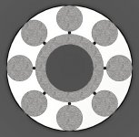
Thanks! My current drawings have the neo placed right up to the edge of the central pole piece. There are eight 2mm OD through holes for venting the VC gap. This is as compact a motor as I can possibly design without having to reduce gap thickness. I haven't got the parts machined yet, so there is room for modification. Here is a sectional view :
Attachments
There are eight 2mm OD through holes for venting the VC gap.
should not be needed with this type of magnet system ... it is naturally 'selfventing', so to speak

Thanks! My current drawings have the neo placed right up to the edge of the central pole piece.
I would be careful with that, and instead getting them away from the magnet gap
That's why *everybody* uses roughly 10% smaller plates.
And it's easy to say why: again using my real world measurements, "retracting" plates by 6 mm doubles the outside gap path and halves loss ..... how's that ?
By the way, even sreten's picture shows that
Thanks for the very clear explanation. In that case I could retract the plates by 6mm. Pole pieces shrink from 92.1mm OD to 80.1mm. The neo magnets will overhang the outside edge by 6mm. Thus, I have about 1/3 the magnet sticking out. Magnet OD is 19.05mm. Thus, should the overhang be calculated as a percentage of the surface area of the magnet? (top circular section).
I read up on some neo designs and they claim that the flux in neo's are more efficiently channeled than in a ferrite or alnico magnet. Worth further investigation.
Are you familiar with femm? i suggest you to play with it for a while (magnet2d/3d is also useful), it'll give you
some idea how to start.. saturation depends on the material. Finemotor is also great.
I've downloaded FEMM. Going through their tutorials right now!
"150 watt continuous power handling"
this is very hard to predict.. depends on VC diameter, cooling, wire gauge (enclosure type?) etc..
Indeed. Actually 150W is too optimistic because this is an underhung design. The short coil (5mm) cannot dissipate heat as well as an overhung coil (15mm). I estimate around 80W before the enamel in the wires melt. Although if there is sufficient flux in the gap, the 20mm pole piece gives me flexibility to use various coil lengths and motor topologies.
those magnets are very dangerous.. i wouldn't try to assemble them in a magnetized state.. let me know if you have been successful
Yeah very dangerous. I'll use spacers and gloves for safety. There won't be an issue assembling the motor. The only problem is disassembling the pole pieces to test a different VC gap.
flux lines flow in the lower magnetic resistance (remanence) as in electronics, however stray flux can be used to add up to the useful BL
Yes I have seen this in overhung motors. Helps to extend X-Max a little.
Good drawings, anyway!
Thank you! I really am terrible at drawings.
[/QUOTE]
Hi,
Don't confuse issues that relate to ferrite with AlNiCo or Neo.
The distance of the pole plates to the edge of a ferrite depends
on the loss of the field around the edge compared to effective
use of the ferrite magnet, and 6mm is too much, you will lose
more effective magnet that you will gain in reducing losses,
with the quoted 15mm thick magnet.
rgds, sreten.
what if the neo were stacked and put in to replace the pole piece?
They stil need a magnetic circuit for the flux to flow around.
The top pole piece is shaped to give that near saturated flux level across the gap to the outer pole piece.
The backplate and the outer cylinder are sized to give lowish flux density in the chosen steel material.
But the pole diameter and thus voice coil diameter, is limited to slightly larger than the neo diameter.
Definitely possible, but limited to a much lower power handling transducer like a tweeter/small fullrange since the price of neo rises "exponentially" as the diameter increases!
One issue is heat since the pole surface area is much smaller and the neo's start losing some of their strength after 80 Deg C. Pole piece venting will be difficult or if successful, will reduce the neo strength.
The idea is perfect for small fullrange speakers that have to be extremely compact and low profile. Used in TV's / iPod Docking stations.
Here is a thread on using the stacked neo's for a sub : Subwoofer stacked neo
Simply crazy. I would be anywhere near that magnet!
By the way, even sreten's picture shows that
Hi,
FWIW I somewhat disagree with some aspects of your analysis,
but you have pointed out some basic flaws in what I said.
Clearly a ferrite magnetic system has the gap flux and the leakage
flux around the driver. Cheap drivers that don't saturate any increase
in leakage flux will reduce gap flux. Drivers that do saturate the poles
are much less effected by increases in the leakage flux, they can cope.
For ferrite I've always said overhang is pointless, and you are right
in that its a question of balancing the outside loop flux lost versus
effectively using the magnet, ferrite, anisotropic, doesn't do sideways.
rgds, sreten.
However what is good design is not a MUST, its just sensible.
should not be needed with this type of magnet system ... it is naturally 'selfventing', so to speak
Agreed. That is just an "extreme" version with the 8 holes.
I would be careful with that, and instead getting them away from the magnet gap
Ok. I will re-size the pole pieces.
Hi,
Don't confuse issues that relate to ferrite with AlNiCo or Neo.
....and 6mm is too much, you will lose
more effective magnet that you will gain in reducing losses,
with the quoted 15mm thick magnet.
rgds, sreten.
Spot on. Thanks.
Simply crazy. I would be anywhere near that magnet!
Should read " would not".
also read this:
K&J Magnetics Blog
according to the site, the maximum op. temp for neo is given by the thickness (for free air at least) i don't know whether it is true for a speaker assembly
K&J Magnetics Blog
according to the site, the maximum op. temp for neo is given by the thickness (for free air at least) i don't know whether it is true for a speaker assembly
femm tutorial (if you haven't found it yet):
Finite Element Method Magnetics: Analysis of a Woofer Motor
magnet2d/3d (trial):
MagNet Trial Edition
Analyzing a loudspeaker design
Finite Element Method Magnetics: Analysis of a Woofer Motor
magnet2d/3d (trial):
MagNet Trial Edition
Analyzing a loudspeaker design
Ahh, brings back memories. I remember going through this malarkey a while back
Your motor design will be near pointless (other than for academic purposes), and you'll see why once you model it in FEMM.
There was an excellent thread a few years back (nearly a decade ) which had some excellent general discussion on motor/speaker building: DIY Parthenon
No doubt you've read this and this.
Also see the bottom of this page for a FEMM designed model, and this page might give you an idea what to expect by randomly putting parts together with some NEO magnets.
Best of luck, V
Your motor design will be near pointless (other than for academic purposes), and you'll see why once you model it in FEMM.
There was an excellent thread a few years back (nearly a decade
) which had some excellent general discussion on motor/speaker building: DIY ParthenonNo doubt you've read this and this.
Also see the bottom of this page for a FEMM designed model, and this page might give you an idea what to expect by randomly putting parts together with some NEO magnets.
Best of luck, V
Last edited:
K&J are doing a special offer on 50mm diameter 25mm thick N35 magnets. They are cheaper than 8 off 3/4" * 3/8".
K&J Magnetics - Products
K&J Magnetics - Products
- Status
- This old topic is closed. If you want to reopen this topic, contact a moderator using the "Report Post" button.
- Home
- Design & Build
- Parts
- Axial or Diametrical neo magnets for homemade speaker?