Hmm, I am missing a crucial piece of info here, how does the AR decide the atten step?You are correct that the DC at TP12 is the value that will be displayed, but it is modified by the attenuation that the controller think is in force.
If you do the test with the attenuation manually set to 0dB it should be the same.
I'll look into it today.
Jan
The way I believe it works is that the AR senses and measures the input voltage, through the LTC RMS converter and then the controller receives the DC value output to decide the atten ratio to use - if this is the case, there has to be an interruption somewhere, given that, although we found out my LTC1968 is faulty, and that it produces the wrong output, this "wrong" value is in any case not passed to the controller beyond TP12.
Or, does it measure input voltage differently than this?
Would you suggest I disassemble the boards and try to see the signal paths to see where it goes wrong? I kind of have to do it anyway to replace the LTC chip...
The controller looks at the DC at TP12 to see if it is higher or lower than the output level you have selected.
If TP12 is higher, it increases the attenuation, and vice versa.
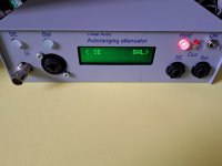
That is why I suggested to do a final test with the attenuation set manually at 0dB, and input 1V at the SE input.
It should then display 1V Vout.
I will send you a new LTC1968, and then we repeat the above. I wouldn't start taking it apart yet. That's a last resort, and has the risk of damaging what is OK.
Patience my friend ;-)
Jan
If TP12 is higher, it increases the attenuation, and vice versa.
That is why I suggested to do a final test with the attenuation set manually at 0dB, and input 1V at the SE input.
It should then display 1V Vout.
I will send you a new LTC1968, and then we repeat the above. I wouldn't start taking it apart yet. That's a last resort, and has the risk of damaging what is OK.
Patience my friend ;-)
Jan
Documentation update: Matthias Carstens has updated his test and measurements of the autoranger: https://linearaudio.nl/sites/linearaudio.net/files/AutoRanger Version 3 Tech Specs MC JD 6c.pdf
I believe the measurements speak for themdselves.
Jan
I believe the measurements speak for themdselves.
Jan

or as us pedants say: "res ipsit loquitor"I believe the measurements speak for themdselves.
Hello Jan,The controller looks at the DC at TP12 to see if it is higher or lower than the output level you have selected.
If TP12 is higher, it increases the attenuation, and vice versa.
That is why I suggested to do a final test with the attenuation set manually at 0dB, and input 1V at the SE input.
It should then display 1V Vout.
I will send you a new LTC1968, and then we repeat the above. I wouldn't start taking it apart yet. That's a last resort, and has the risk of damaging what is OK.
Patience my friend ;-)
Jan
I enjoyed building your MKII V3.19 rel-2 kit, the 10k Zin version, of your Autoranging Attenuator. This is my first contact with the DIY Audio forums (other than to participate in a group buy) and I want to express my appreciation for the detailed suggestions you have made to other builders of the Attenuator, in particular reddish75. While testing my Attenuator, I found a glitch that I haven’t seen mentioned in the posts, so I thought it may be useful to others to know what I found.
Following your suggestions to DIYAudio member reddish75, I made the measurements you asked him to make, and I list my results here (somewhat like reddish75, but not identical):
With 1V RMS into BNC (Manual mode, gain at 0 dB):
Signal at TP1 = .996V
Signal at TP15 = .995V
Signal at TP16 = .6mV
SE output = .996V
TP12 = 1.55V (DC)
TP17 = .58mV
TP18 = .996V
TP19 = .996V
Top of R15 = .50V
C10, left end, 97mv (AC)
C12, left end, floating? 1mV (DC)
With 1V RMS going in unbalanced, gain at 0dB, 1V is coming out unbalanced.
As I was getting ready to measure the AC input and DC output of the LTC1968, as you suggested in your post of 2022-03-18 8:31 a.m., and as I was locating pin 2 and pin 5 of the LTC1968, I noticed a problem with the LTC1968: pins 1 – 4 were not soldered. The chip was “floating” above its pads for pins 1 – 4 but was secured in place on the board by (soldered) pins 5 – 8.
This was my first time soldering a package the size of the LTC1968, but after getting the chip soldered, I turned on the unit and it seems to work perfectly now. Very gratifying, and thank you again for your detailed trouble-shooting instructions!
Peter
Everything else works,That's odd. Do the other functions work? Can you change the attennuation in Hold mode with the SE and Bal pushbuttons?
Jan
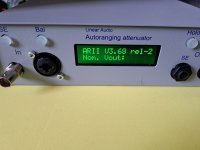
Hi, Display: V5 Att MKII 3.19 PIc: ARII 3.19 rel-2Can you tell me the version number on the display board, is it V5?
And the atten board, and the label on the controller?
Jan
Jan hi,
What the 50mA/250V cylindrical fuses are protecting in the Autoranger?
I blew one of those during a 100W amp's overdrive mishap in SE (fuse near the 16 pins driver chip).
The AR was still displaying and its buttons were functioning but it could not read or pass input signal anymore.
Just in a circle of ratio hunt clicking if not set on hold. The rails status Leds were on. Correct rails voltages, op-amps good, no blown traces. Just that fuse was testing open and I replaced it with a spare. Then the AR went back to normal.
So this was one rare case where a fuse actually did what it was intended to do! Very often the equipment dies to protect the fuse ;-)
The fuse is in the signal path between the high level attenuator and the low level attenuator (above 0dB).
So naturally all power indications and the logic work normal even when it is blown, but since the signal path is interrupted, the level logic is panicking.
Jan
The fuse is in the signal path between the high level attenuator and the low level attenuator (above 0dB).
So naturally all power indications and the logic work normal even when it is blown, but since the signal path is interrupted, the level logic is panicking.
Jan
I am glad that the fuse did what it was intended to do. The rapid overdrives happened because I tried the Rightmark automated measurement suite on that amp. Bad idea. The AR didn't like the software's abrupt switches from nothing to near dBFS test signal sequences. Especially when fed through a 100W power amp. Luckily the amp survived too.
Those fuses show 4.3Ω when healthy. There could nonetheless exist some tiny non-linearity added by them in the signal path for large input swings? Because of their fusible element ppm and such. Not something that I could ever measure with a cost friendly home studio interface. And they proved really useful. Academically speaking, if existing, theirs would be around or even below the op-amps non-linear contribution if testing with an AP modern station?
It's in series with a very high impedance so any possible linearity is divided by that 4.3R and the series impedance.
Some thought experiments: assume 4.3R is 0.1% nonlinear which is -60dB. In series with 430k that's 4.3/430,000 = another -100dB, so total -160dB.
I've never been able to measure that ;-)
Jan
Some thought experiments: assume 4.3R is 0.1% nonlinear which is -60dB. In series with 430k that's 4.3/430,000 = another -100dB, so total -160dB.
I've never been able to measure that ;-)
Jan
- Home
- Design & Build
- Equipment & Tools
- Autoranger for soundcards