https://www.newhavendisplay.com/nhd0216k1znsrgbfbwrev1-p-2844.html*Characters ain't trully white in my pics but RGB. Its the close up brightness that throws the phone's color balance off.What is the part number for the green / white text display?
This is a very good solution, thanks for that!
For the next batch I shall adapt the footprint so both will fit.
The different versions are only for compatibility with some NEC and other brand relays. Absolutely electrically the same.
BTW Nice clean soldering on the opamps.
Jan
For the next batch I shall adapt the footprint so both will fit.
The different versions are only for compatibility with some NEC and other brand relays. Absolutely electrically the same.
BTW Nice clean soldering on the opamps.
Jan
Hi Jan,This is a very good solution, thanks for that!
For the next batch I shall adapt the footprint so both will fit.
The different versions are only for compatibility with some NEC and other brand relays. Absolutely electrically the same.
BTW Nice clean soldering on the opamps.
Jan
thank you! Too bad I did not think to make pics during the bending of the pins....
and it indeed it was a chore to solder the LTC chip - even using chipquick and hot air.
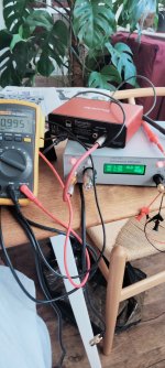
i havent managed to actually test it yet, last thing is finding a BNC that can fit the hole of the pin jack socket for SE operation, the AR just turns on and displays ... well something, i will post a pic once I get back home ad I am traveling for work , so maybe you can tell me if everything is OK.
for now I’m satisfied!

basically yes all this values with no input, just stand alone. if i short the bnc input nothing happens values stay the sameSo you have all these values without any input signal?
What do you get if you short the BNC input and select SE input?
Jan
OK, time for some diagnostics! Please connect a 1V source, 1kHz, to the SE input.
Select HLD, then use the SE and Bal buttons to set the unit to 0dB.
What output level do you measure at the SE output?
Jan
1v at 1khz output at se is 0.995v display shows vo as 1.29 and vi as 1.29 so it needs calibrating?
Attachments
Last edited:
There's no calibration. Do you have the User Guide?
I'll send you some test points later today.
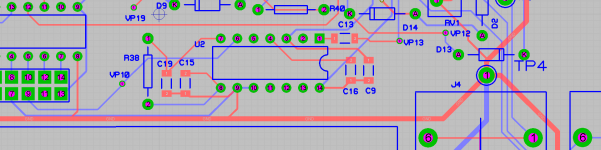
Edit I'll do it right now. With the 0dB 1V situation as above, please measure the AC signal at pin 1 of U2, the AD635.
Be careful not to short any pins.
Also measure DC voltage at test point VP10 as shown.
You can use TP4 as the ground pin for your meter.
Jan
I'll send you some test points later today.
Edit I'll do it right now. With the 0dB 1V situation as above, please measure the AC signal at pin 1 of U2, the AD635.
Be careful not to short any pins.
Also measure DC voltage at test point VP10 as shown.
You can use TP4 as the ground pin for your meter.
Jan
Attachments
Last edited:
Thanks I'll try and get this done later today.There's no calibration. Do you have the User Guide?
I'll send you some test points later today.
Edit I'll do it right now. With the 0dB 1V situation as above, please measure the AC signal at pin 1 of U2, the AD635.
Be careful not to short any pins.
Also measure DC voltage at test point VP10 as shown.
You can use TP4 as the ground pin for your meter.
Jan
Hi JanThere's no calibration. Do you have the User Guide?
I'll send you some test points later today.
Edit I'll do it right now. With the 0dB 1V situation as above, please measure the AC signal at pin 1 of U2, the AD635.
Be careful not to short any pins.
Also measure DC voltage at test point VP10 as shown.
You can use TP4 as the ground pin for your meter.
Jan
AC signal voltage at pin 1 on U2 is 0.997v
DC at vp10 is 1.009V
These values are correct, so that part works.Hi Jan
AC signal voltage at pin 1 on U2 is 0.997v
DC at vp10 is 1.009V
With the signal input at 1V and 1V out at 0dB, if you change the setting to -6dB, does the output drop to about 0.5V?
Jan
Yes, that's how it looks, that there's an issue with a relay. The software works, the analog chain works, the RMS to DC converter works.
I can think of two possible issues: the -6dB relay K2 is inserted wrong way around, or the flat cable between the two boards has an issue.
Let's try another relay, K3. With 1V in, 0dB and 1V out, switch the setting to -12dB. If K3 works (and the flat cable is OK) the output should drop to about 0.25V.
It's anyway a good idea to check polarity of the relays and the seating of the flat cable.
Jan
yes at -12, correct seems k3 works as voltage drops to 0.25v.
Cable seems to be pushed all the way down and in. Orientation of relay seems fine?


Yes correct seems k3 works as voltage drops to 0.25v.
Cable seems to be pushed all the way down and in. Orientation of relay seems fine?

Cable seems to be pushed all the way down and in. Orientation of relay seems fine?
Yes, that's how it looks, that there's an issue with a relay. The software works, the analog chain works, the RMS to DC converter works.
I can think of two possible issues: the -6dB relay K2 is inserted wrong way around, or the flat cable between the two boards has an issue.
Let's try another relay, K3. With 1V in, 0dB and 1V out, switch the setting to -12dB. If K3 works (and the flat cable is OK) the output should drop to about 0.25V.
It's anyway a good idea to check polarity of the relays and the seating of the flat cable.
Jan
Yes correct seems k3 works as voltage drops to 0.25v.
Cable seems to be pushed all the way down and in. Orientation of relay seems fine?
Last edited:
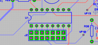
Yes seems fine. Can you verify that the command to relay K4 switches when you go from 0dB to -6dB, pin 16 of U1 (the relay driver).
If that works, it might be the K4 relay or possibly a forgotten solder pin on K4, happens to the best of us.
If that doesn't work it might be a wire of the flat cable not correctly connected.
In that case, check that the relay command switches at pin 11 of the processor chip, this is not easy to test that, be careful of shorts.
You can also check this at pin 2 of the header if you remove the cable from the display board.
Jan
Attachments
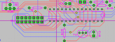
So use tp4 as before with my DMM and measure at pin 16 of U1 in DC?Yes seems fine. Can you verify that the command to relay K4 switches when you go from 0dB to -6dB, pin 16 of U1 (the relay driver).
How do I check the rely command?If that works, it might be the K4 relay or possibly a forgotten solder pin on K4, happens to the best of us.
If that doesn't work it might be a wire of the flat cable not correctly connected.
In that case, check that the relay command switches at pin 11 of the processor chip, this is not easy to test that, be careful of shorts.
Checked soldering and it's all there.You can also check this at pin 2 of the header if you remove the cable from the display board.
Jan
Thanks
Attachments
So use tp4 as before with my DMM and measure at pin 16 of U1 in DC?
Yes
How do I check the rely command?
It should switch between 0 and +5V
Checked soldering and it's all there.
Thanks
- Home
- Design & Build
- Equipment & Tools
- Autoranger for soundcards