The 2.7R and 0.1uF are optional Zobel components and I do not recommend using them, that's why they were not included.
There shouldn't be any 1.5R resistors there, the 3W 0.1Rs are used for parallel configuration only.
You will find more info here: http://www.diyaudio.com/forums/audio-sector/155635-kit-arrived.html
My apologies. I probably read that in this thread a while back and just overlooked it. Here is a pic then of the first board. Both of these will be stereo as I want to make one 4 channel amp, and then the second kit will be wired for 2 channels. How does this look now
An externally hosted image should be here but it was not working when we last tested it.
An externally hosted image should be here but it was not working when we last tested it.
An externally hosted image should be here but it was not working when we last tested it.
An externally hosted image should be here but it was not working when we last tested it.
.
Last edited:
Pics of the PS boards...
An externally hosted image should be here but it was not working when we last tested it.
Are you talking about this one: http://www.diyaudio.com/forums/audi...chip-amp-kits-dacs-chassis-25.html#post785996
hi, i'm new guy here..
i saw theLM3875 Amplifier Kit user guide in DIY Chip Amplifier Kits, PCB's, Components and Information.
it seems that the amplifier is using 2 pairs of RCA input. L&R on the first PCB, and L&R on the second PCB. why is that? what if i want to use gainclone as headphone amp?
*noob question, sorry
i saw theLM3875 Amplifier Kit user guide in DIY Chip Amplifier Kits, PCB's, Components and Information.
it seems that the amplifier is using 2 pairs of RCA input. L&R on the first PCB, and L&R on the second PCB. why is that? what if i want to use gainclone as headphone amp?
*noob question, sorry
On which page?
That user guide is seriously outdated though, for current info please see this link: http://www.diyaudio.com/forums/audi...cial-gainclone-kit-building-instructions.html
That user guide is seriously outdated though, for current info please see this link: http://www.diyaudio.com/forums/audi...cial-gainclone-kit-building-instructions.html
On which page?
That user guide is seriously outdated though, for current info please see this link: http://www.diyaudio.com/forums/audi...cial-gainclone-kit-building-instructions.html
i downloaded the user guide from audiosector.com
from here: DIY Chip Amplifier Kits, PCB's, Components and Information.
if i want to use gainclone using headphone as the output, so i will only need 1 pcb kit instead of dualmono?
If you are using LM3875 kit, you still need 2 amp boards, but single supply (instead of dual mono) will work fine.
More info about LM3875 as headphone amp can be found here: http://www.diyaudio.com/forums/headphones/62828-lm3875-headphone-amp-another-try.html
More info about LM3875 as headphone amp can be found here: http://www.diyaudio.com/forums/headphones/62828-lm3875-headphone-amp-another-try.html
If you are using LM3875 kit, you still need 2 amp boards, but single supply (instead of dual mono) will work fine.
More info about LM3875 as headphone amp can be found here: http://www.diyaudio.com/forums/headphones/62828-lm3875-headphone-amp-another-try.html
do i still need the rectifier board? and then connect it to the transformer?
where can i buy a good and cheap transformer?
Unless using batteries, the rectifier board is always needed.
You may try Antek transformer on Ebay or check with Apex Jr: miscellaneous.html
You may try Antek transformer on Ebay or check with Apex Jr: miscellaneous.html
Attachments
Unless using batteries, the rectifier board is always needed.
You may try Antek transformer on Ebay or check with Apex Jr: miscellaneous.html
should i go with a transformer or toroid? which transformer model is most suitable for LM3875 dual mono kit?
i read the building instructions and saw on the picture that each pcb output is connected to L&R RCA. 2 pcb will be 2 of RCA pairs while i only need 6.3mm headphone output. how do i solve this problem?
For headphones it doesn't matter much, choose most convenient option.
For the amp I usually recommend 300VA, 2 x 22V toroids, for headphones 100VA should be fine.
Regarding wiring problem, check those links for details:
TRS connector - Wikipedia, the free encyclopedia
How to make a headphone jack to RCA cable or adapter? - Yahoo! Answers
How does a RCA(White/Red) to headphone jack cable work? - Yahoo! Answers
http://www.diyaudio.com/forums/headphones/122785-1-4-headphone-jack-wiring.html
For headphones it doesn't matter much, choose most convenient option.
For the amp I usually recommend 300VA, 2 x 22V toroids, for headphones 100VA should be fine.
Regarding wiring problem, check those links for details:
TRS connector - Wikipedia, the free encyclopedia
How to make a headphone jack to RCA cable or adapter? - Yahoo! Answers
How does a RCA(White/Red) to headphone jack cable work? - Yahoo! Answers
http://www.diyaudio.com/forums/headphones/122785-1-4-headphone-jack-wiring.html
my headphone needs 4W at 100 ohm impedance. so 100VA transformers will do? how do i know the transformer's power is sufficient for powering my headphone?
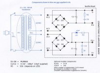
i looked at the schematic again, and ended up confused with the output channel:
http://i61.photobucket.com/albums/h75/soesnake/Home%20Audio%20Projects/AmpKit003.jpg
the picture is showing 1 PCB. it's clearly written there are 2 output channels. if i build a LM3875 kit i will have 2 PCB with same output, meaning there will be 2 left & 2 right channel right? while the headphone jack will only need 1 left, 1 right, & 1 ground channel. How do i do the wiring?
Last edited:
Are you talking about this one: http://www.diyaudio.com/forums/audi...chip-amp-kits-dacs-chassis-25.html#post785996
thats the one haha, looks very nice
- Status
- This old topic is closed. If you want to reopen this topic, contact a moderator using the "Report Post" button.
- Home
- More Vendors...
- Audio Sector
- AudioSector-chip amp kits, dacs, chassis