Peter Daniel said:
There is approx 1V drop on 20R resistors, since you need to drop 5V, your resistors should be approx 100R, but you still need to check it in a working circuit.
Ok, let me think a bit about that, just for fun...
3. If a 2x9V trans would be fine without any changes, we could say I only need a 4V drop.
3. My 2x12V trans is a 120VA type, so it will provide a slightly better regulation than the 48VA trans, with a lower open circuit voltage. So perhaps I only need a 3V drop in total, and 68 ohm resistors might be absolutely fine?
If I want to measure this, which voltage should I measure after the resistors?
Thanks - martinbls
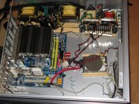
Peter Daniel said:There were some inquieries with regards to linear PS I used in this setup: http://www.diyaudio.com/forums/showthread.php?postid=1787133#post1787133 so here's the schematic.
LT1083CP-12 seem to be hard to get these days; I got mine directly from Linear Technology as samples. Both the regulator and diodes need to be mounted on a heatsink.
I remove two small caps from picoPSU and installed there single BG N 470/16
Peter,
Thanks for posting this. I'm going to copy the info into the cMP mod thread that I started over in the digital source forum. Your PS was one of the inspirations for my experiments in linear-based hybrid PS's for computer audio and they have been very successful.
Greg in Mississippi
Attachments
Peter, If I wanted to add a balanced input to your amp, how and where would i do this? (not using an adapter) I understand it would mean using a switch to go from stereo to mono, and which speaker out would I use, or would I need a dedicated third.
Sorry for the naive questions - this is my first build - yee ha!
Sorry for the naive questions - this is my first build - yee ha!
Peter,
I was wondering if you ever investigated the idea of asynchronous USB Audio. I know Gordon Rankin of Wavelength Audio has it in all of his 1543 based dacs. It looks very interesting. In addition he has a low jitter oscillator thrown in. However, its very, very expensive.
Here is the link for more info.
Best,
Anand.
nycavsr2000 said:I was wondering if you ever investigated the idea of asynchronous USB Audio. I know Gordon Rankin of Wavelength Audio has it in all of his 1543 based dacs. It looks very interesting. In addition he has a low jitter oscillator thrown in. However, its very, very expensive.
He uses custom software which is beyond my scope. Yet, it needs to be determined how much actual improvement it really brings (everything else being equal).
nobu said:Peter, If I wanted to add a balanced input to your amp, how and where would i do this? (not using an adapter) I understand it would mean using a switch to go from stereo to mono, and which speaker out would I use, or would I need a dedicated third.
You would need two stereo amps and XLR --> 2 x RCA adaptor. You also need balanced source, if you don't have one the easiest way to convert unbalanced signal to balanced would be with transformers: http://www.diyaudio.com/forums/showthread.php?postid=1712724#post1712724
PD phono preamp project completed
Peter-
I have to thank you for publishishing your phono preamp circuit back in 2007.
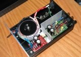
I've finally finished building a phono preamp based on your suggestions, but not dual mono power supples. It sounds great, and hasn't broken in yet.
Details and photos here:
http://mpbarneysources.googlepages.com/peterdanielphonopreamp
Best regards,
Mike
Peter-
I have to thank you for publishishing your phono preamp circuit back in 2007.
I've finally finished building a phono preamp based on your suggestions, but not dual mono power supples. It sounds great, and hasn't broken in yet.
Details and photos here:
http://mpbarneysources.googlepages.com/peterdanielphonopreamp
Best regards,
Mike
Attachments
balanced input
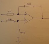
I thought this might be a simpler way to do balanced in
mike")
nobu said:Peter, If I wanted to add a balanced input to your amp, how and where would i do this?
I thought this might be a simpler way to do balanced in
mike
Attachments
Re: PD phono preamp project completed
Hi Mike, very nicely done and well documented.
I didn't use those diodes, but here's the pic with TO-220 diodes and you can easily figure out where cathodes go on 1N4007: http://www.diyaudio.com/forums/showthread.php?postid=1237672#post1237672
mikebarney said:
I've finally finished building a phono preamp based on your suggestions, but not dual mono power supples. It sounds great, and hasn't broken in yet.
Hi Mike, very nicely done and well documented.
woodturner-fran said:Peter - would you have a pic of one of your power supply boards from the F4/F5 group buy where you fitted ordinary 1N4007 type rectifiers.
I didn't use those diodes, but here's the pic with TO-220 diodes and you can easily figure out where cathodes go on 1N4007: http://www.diyaudio.com/forums/showthread.php?postid=1237672#post1237672
Re: balanced input
The inverting input impedance is 10k.
The non inverting input impedance is 160k.
no.mikelm said:I thought this might be a simpler way to do balanced in
The inverting input impedance is 10k.
The non inverting input impedance is 160k.
Re: balanced input
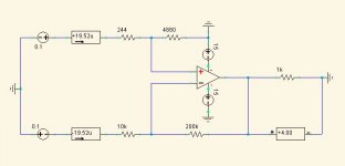
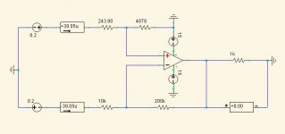
Yeah your right - I played about it spice and came up with this. It seems weird but the current meters on the input seem to be indicating equal i/p impedance.
i/p impedance = about 5.123K ohms each leg
Can you see any problems with this ? I can't but perhaps Iv'e lost the plot somewhere.
mike
AndrewT said:The inverting input impedance is 10k.
The non inverting input impedance is 160k.
Yeah your right - I played about it spice and came up with this. It seems weird but the current meters on the input seem to be indicating equal i/p impedance.
i/p impedance = about 5.123K ohms each leg
Can you see any problems with this ? I can't but perhaps Iv'e lost the plot somewhere.
mike
Attachments
simpler method
.
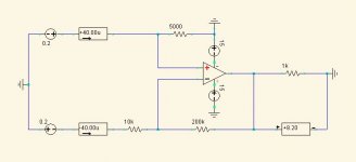
This however is a simpler and more practical circuit.
Sorry to clutter your thread up with this stuff Peter but I just figured this stuff out and although it may be old hat to some of you guys for me it's breaking news.
Of course this would only work from a low impedance source so perhaps it is not as simple as I originally thought but hopefully it may be of some interest
mike
.
This however is a simpler and more practical circuit.
Sorry to clutter your thread up with this stuff Peter but I just figured this stuff out and although it may be old hat to some of you guys for me it's breaking news.
Of course this would only work from a low impedance source so perhaps it is not as simple as I originally thought but hopefully it may be of some interest
mike
Attachments
None of those are balanced circuits.
All have a higher impedance at the inverting input (about 2times) than at the non-inverting input.
edit:
it's more usual when using both inputs for the inverting input to be the lower impedance, your's are swapped and relatively easy to make near equal impedance. But, never accurate enough to give effective balanced operation.
Hi Andrew,
I'm grateful that you raised this because there were several issues that I was not aware of so I spent quite a while last evening playing in spice and doing some calculations and now these issues are quite clear to me.
For the last two spice diagrams I have posted I can assure you that the i/p impedance for a differential signal is equal for both legs - this is evident by the fact that you can see I applied equal & opposite voltages & measured equal & opposite currents.
I checked the maths on this and it checked ok
However these circuits do not have equal impedance for a common mode signal i.e. noise and more importantly common mode noise does not cancel so even though it was interesting to check out these ideas I do not believe they would practically sound very good either in applications were pick up was trying to be avoided or where pre-existent common mode noise needed to be canceled.
The first circuit I posted ( hand drawn ) gives more or less perfect common mode impedance & cancellation so even though the differential currents where unbalanced I suspect that this cct would still sound very good where it is important to cancel common mode noise e.g. from a balanced DAC o/p especially if leads where short and pick up was not an issue.
In this circuit one can add in a resistor from the non inverting i/p leg of about about 5K to ground - this gives good differential balanced impedances and amplification and common mode cancellation but not common mode balanced impedances This option might be worth checking out for sound quality.
So that's that ! I suspect that different versions would sound best with different applications but in the true sense, none of them are perfectly balanced in all regards. For that one would indeed need a either two separate amplifiers with identical inputs as Peter suggested or a transformer.
I appologise again to for inserting all this OT stuff in the middle of Peter's thread but hopefully it wasn't only me who learnt something
- Status
- This old topic is closed. If you want to reopen this topic, contact a moderator using the "Report Post" button.
- Home
- More Vendors...
- Audio Sector
- AudioSector-chip amp kits, dacs, chassis