It uses E2140 and the system is based on manual posted here: http://photos.imageevent.com/cics/v... art of building Computer Transports v0.3.pdf
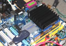
In my main setup, I switched to E7200 chip with Gigabyte motherboard, which is better. It also runs very cool and only small heatsink is required (no fan need).
In my main setup, I switched to E7200 chip with Gigabyte motherboard, which is better. It also runs very cool and only small heatsink is required (no fan need).
Attachments
Peter Daniel said:
<SNIP>
In my main setup, I switched to E7200 chip with Gigabyte motherboard, which is better. It also runs very cool and only small heatsink is required (no fan need).
Peter,
I'm very interested to see where you go with your main system unit.
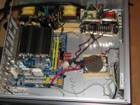
I was inspired by your earlier version and recently powered my cMP2 with 4 seperate linear supplies... two based on 100VA Hammond transformers powering the PicoPSU and the P4 connection on the motherboard and two smaller ones powering the harddrive, USB, and touchscreen. Adding these provided a significant improvement in sound quality.
I'm currently sorting out my D-to-A conversion optionstrying a few options, but one of my next goals is to make a case that will do a better job than the Zalman in controlling vibration and shielding the various sections from each other.
Thank you for providing the link to cics's work and for your inspiration in how to improve it further!
Greg in Mississippi
P.S. I know this is your thread, but this is worth a separate thread to discuss further. Interested?
Attachments
Peter, glad to see you doing some work in the PC field, always
interesting to see what you come up with! : )
I would love to build a PC using Cics guidelines - but until someone
can come up with a simple PARTS LIST of AVAILABLE hardware
it seems impossible.
With each passing month Motherboards, RAM, and CPUs are discontinued
or not stocked anymore.
Since low wattage parts and BIOS upgrades are needed to tweak
the PC for good sound, it seems almost impossible to play along
unless you were in on the ground floor.
The computer industry thrives on hyper-evolution!, i can't see
this problem getting any better. Later this year Windows XP will be pushed
back another generation by Windows 7. This problem needs to be
addressed for the longevity of this project.
moe29 said:I would love to build a PC using Cics guidelines - but until someone
can come up with a simple PARTS LIST of AVAILABLE hardware
it seems impossible.
I,ve already mentioned it before: everything can be found on ebay, even if the product has been discontinued long ago.
")
Greg Stewart said:P.S. I know this is your thread, but this is worth a separate thread to discuss further. Interested?
Sure, if you start a separate thread, I can post there.

Peter Daniel said:
Sure, if you start a separate thread, I can post there.
See here:
Digital Source cMP2 Mods Thread
Post away. I'll put in more about my power-supplies later this week.
Greg in Mississippi
passive pre for lm3875
Hi Peter,
finally I am ready to built my "reference" stereo amp with the premium lm3875 kit I got from yoy some months ago. I am a newbie but I have quite clear ideas on the amps thanks to your thread on gainclone for beginners and I built a simple lm1875 amp for exercise which is working fine.
On the contrary I am a little bit confused on the passive pre I intend to built for volume setting and input selection.
For proper matching with sources I read a lot about the importance of the input impedance of the amp: what is the input impedance of a monoblock with your premium kit?
In your manuals you showed a pot with 50K resistance: is this the proper value to be used?
Can you address me on the net to good quality projects or kits for a passive pre? Also a kit from you would be really welcome.
I apologize for the number of questions, but maybe, being a standard newbie, my questions are common to other newbies (the pre topics is the only issue that I found nor covered in your excellent thread on commercial gainclone for beginners)
Renato
The input impedance of the amp is set by R2 which is 22k.
I often use 50k pots and they work fine; normally I recommend 25K value though.
I wouldn't really encouraghe separate passive preamp projects. While there's nothing wrong with them, it's much better to integrate the amp, potentiometer and source selector in one enclosure, which becomes an Integrated amp: http://audiosector.com/chassis_integrated.shtml
The Integrated amp from link above is available as a kit, either complete package or selected components.
Thank you for your quick reply Peter.
So, do you prefer a pre with gain or a buffer for your Patek amp?
Renato
I wouldn't really encouraghe separate passive preamp projects.
So, do you prefer a pre with gain or a buffer for your Patek amp?
Renato
The best thing for Patek was switched attenuator built in directly in the amp, no buffers or preamps with gain:
An externally hosted image should be here but it was not working when we last tested it.
An externally hosted image should be here but it was not working when we last tested it.
An externally hosted image should be here but it was not working when we last tested it.
Hi Peter,
i have a few more questions on your LM3875 amp and USB DAC (I will place my order for the DAC in a few days!).
1. If I use a toroid trans with 2x12V secondaries to power the DAC, to which value should I increase the series resistors? You are using 20ohms as I understand, would something like 47ohms be suitable, or even larger, to ensure the 8V regulators run rather cold?
2. If I put the amp and the DAC in one case, with just a 50kohm pot between, then I won't need a input coupling cap for the amp, because the DAC has a pair of BGs as output coupling caps. But what about the input resistor R1 on the amp board? Would you advise me to omit this resistor completely in this case? Or may there problems occour?
3. If the input impedance of the amp is set by R2 with 22kohm, would it be a good idea to increase R2 to a larger value bacause of the rather highish output impedance of the DAC to ensure better impedance matching, or do you find this useless?
Thanks for answering so many questions, but I always like to have some theoretical backround before starting my own experiences in practise ;-)
Regards - Martin
Hi Guys!
This is a question for all of you who build an integrated amp with BUILD IN DAC, using additional windings from the main toroid transformer.
In this configuration the amp and DAC are switched on and off simultanously. Normally, to prevent any kind of switch-on-noise or plopps, I switch on the computer first, then the DAC, and finally the amp. What about this setup? Is there any noise when switching on the complete amp/DAC unit?
Thanks a lot - Martin
martinbls said:What about this setup? Is there any noise when switching on the complete amp/DAC unit
Yes, there is a noise. One way to avoid it is to switch the amp on with selector set to other source than DAC. I normally don't switch the amp at all, so I'm not really concerned with that thump (which is much louder at turn off than on).
Such amp was presented here: http://www.diyaudio.com/forums/showthread.php?postid=1491212#post1491212
Re: stepped attenuator
This is not a standard product and I only built them for Patek Integrated. The Elma switch is $60 and each Caddock resistor (48 needed) $4/pc. Additionally there were two series Vishays S102 at $12/pc.
northernsky said:the stepped attenuator in you last picture looks very beautiful and seems built with high quality parts. Do you also sell it? In this case what is the price?
This is not a standard product and I only built them for Patek Integrated. The Elma switch is $60 and each Caddock resistor (48 needed) $4/pc. Additionally there were two series Vishays S102 at $12/pc.
martinbls said:1. If I use a toroid trans with 2x12V secondaries to power the DAC, to which value should I increase the series resistors? You are using 20ohms as I understand, would something like 47ohms be suitable, or even larger, to ensure the 8V regulators run rather cold?
2. If I put the amp and the DAC in one case, with just a 50kohm pot between, then I won't need a input coupling cap for the amp, because the DAC has a pair of BGs as output coupling caps. But what about the input resistor R1 on the amp board? Would you advise me to omit this resistor completely in this case? Or may there problems occour?
3. If the input impedance of the amp is set by R2 with 22kohm, would it be a good idea to increase R2 to a larger value bacause of the rather highish output impedance of the DAC to ensure better impedance matching, or do you find this useless?
Thanks for answering so many questions, but I always like to have some theoretical backround before starting my own experiences in practise ;-)
There is approx 1V drop on 20R resistors, since you need to drop 5V, your resistors should be approx 100R, but you still need to check it in a working circuit.
Yes, I would omit R1 completely.
If you increase the value of R2 the offset will also increase substanitially, that's why it's not recommended. If you have DAC and amp in a same case, there are no interconnects involved and it's much easier for a DAC to drive the next stage.
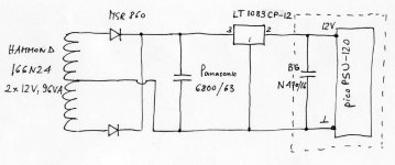
There were some inquieries with regards to linear PS I used in this setup: http://www.diyaudio.com/forums/showthread.php?postid=1787133#post1787133 so here's the schematic.
LT1083CP-12 seem to be hard to get these days; I got mine directly from Linear Technology as samples. Both the regulator and diodes need to be mounted on a heatsink.
I remove two small caps from picoPSU and installed there single BG N 470/16
LT1083CP-12 seem to be hard to get these days; I got mine directly from Linear Technology as samples. Both the regulator and diodes need to be mounted on a heatsink.
I remove two small caps from picoPSU and installed there single BG N 470/16
Attachments
- Status
- This old topic is closed. If you want to reopen this topic, contact a moderator using the "Report Post" button.
- Home
- More Vendors...
- Audio Sector
- AudioSector-chip amp kits, dacs, chassis