Try moving the wires around?
Hi, I have to say, on my amp the only time I heard humming was when one of the pre-amp tubes was about to fail. Changing all the tubes made that go away on the spot.
You haven't mentioned which version have you built: It is the dual monoblock one, or do they share the power transformer and the boards? Also, which output transformers have you got?
I'd go over both boards and re-low each soldering points (yes it's a major pain to remove them from the finished amp. If that doesn't do it, try moving the wires around?
@petertub yes, speaker hum. There is no transformer hum on this amp. now that was interesting! Removing either preamp tube removed pretty much all hum, With both driver tubes out, I couldn’t tell if the amp was on, same result if I pulled the input preamp tube, dead quiet. I guess that means that the hum is induced in the preamp tubes, most likely the input Hm. Maybe a ground loop with the input circuit?
@fb2017 it seems to have all options, dual pts, dual power boards, extra filtering stage top right on both channels. They have the newest transformers, I had to get an addendum to the manual with the right colour codes. I thus have separate windings for the heaters for each tube (all have been referenced to ground). I havn’t reflowed all solder joints...
I actually have a second amp, in all but tranformers an edison 60, but with smaller transformers and intended for 6v6 or 6l6 tubes, 15 watts. It similarly hums quite a bit...
Removal of driver tubes tells us that hum comes from a point before@petertub yes, speaker hum. There is no transformer hum on this amp. now that was interesting! Removing either preamp tube removed pretty much all hum, With both driver tubes out, I couldn’t tell if the amp was on, same result if I pulled the input preamp tube, dead quiet. I guess that means that the hum is induced in the preamp tubes, most likely the input Hm. Maybe a ground loop with the input circuit?
@fb2017 it seems to have all options, dual pts, dual power boards, extra filtering stage top right on both channels. They have the newest transformers, I had to get an addendum to the manual with the right colour codes. I thus have separate windings for the heaters for each tube (all have been referenced to ground). I havn’t reflowed all solder joints...
I actually have a second amp, in all but tranformers an edison 60, but with smaller transformers and intended for 6v6 or 6l6 tubes, 15 watts. It similarly hums quite a bit...
power tubes and that the power tubes are reasonably matches current.
Is the hum present if shorting plugs ( inputs are shorted ) ? If it hums then i would test another 6922
tube(s) as hum may develop between filament and cathode.
One could also try parallelling the C106 ( last electrolytic cap in the B+ chain) and note the effect.
Last edited:
Ok, reporting back. ")
Without the input tube (left tube from the front) all hum is gone, only slight hiss remained on one channel - replacing that tube fixed the hiss level. It couldn’t be heard before under the hum... there is also slightly crackles during startup when the input tube is not there in that channel. Bad solder joint?
Removing phase inverter removes both hum and hiss, there is the tiniest hum when oressing the ear against the midwiofer. I guess there is very little hum from the power tubes.
After replacing the input thbe, both channels behave exactly the same. Seems there is hum injected in the driver stage I wish I still had my oscilloscope...
Oh, and I get lots of noise when turning up the volume btw, above 50 percent or so, with a powered-on source connected (turned on the volume and turned down my dac, so inputs are connected and playing very faintly, not open.)
I very suspicious of the input wiring, but I’ve looked it over several times and it looks right...
I very suspicious of the input wiring, but I’ve looked it over several times and it looks right...
Last edited:
Shorted inputs will tell if hum originates within the amp or comes fromNo, but I’ll go whip up a pair. That’s for testing the volume-up noise?
the connected equipment.
Troubleshooting is always easier if one can divide the problem area and
thus eliminate some part of the possible culprits.
The world is small. I have JJ-E88CC in close to unlimited supply.Got my plugs, but will need to wait until tomorrow to test... Wife went to bed.
Turns out one 6922 hisses, and one is microphonic. Du säljer tydligen rör i Göteborg? Jag bor i Lerum. Världen är liten ibland.
First time post and only recently found this thread.
I built an Edison 60 kit, and hope my comments add to it.
@Leffler I too had a bad hum from one channel with the other quite noisy. Changed the supplied E88CC's with JJ E88CC's and the hum and noise disappeared.
However..... I do have an interesting effect. I have the volume control fitted and R101/201 removed. With the volume at zero and in most other positions the output on both channels is quite noisy, however when the volume control is at about the 10 O'Clock position the output is “tuned out” and completely free of noise - fortunately it’s where I'd normally have it.
The noise is present regardless of whether the input is connected or open circuit. I've not tried shorting the input.
I've 'scoped the preamp valve outputs and cannot really pin it down, so I'd be interested in your views. The good thing is it can be tuned out so I can live with it.
I did try it without the volume and with R101/201 fitted and it was noisy with or without an input.
For info, the input is connected to an ANK Line 4 line phono preamp kit which is completely silent.
On a separate matter, how good have any of you found the quality of the Edison 60 kit to have been? First, to state that my background is electronic prototyping so I'm used to dealing with most issues and I expected there to be some fettling, but I was surprised at some of the issues with my kit.
Mechanically there's a tolerance issue between the boards and metalwork. The boards initially wouldn’t fit as the valve bases and mounting holes were mm’s out even with the boards pressed hard up against the metalwork. The only way I could get them to fit was to shave few mm’s off the board edges as close to the nearest track as possible (it’s a ground track fortunately), and elongate the board mounting holes about 5mm. The board is still pressed against the metalwork and I was just able to get the valve bases to align between the metalwork holes and board solder holes.
Electronically, I've had to replace the higher power resistors R8, R18, R29, R30 and R31 on both boards. After a few months use they were all very discoloured/burnt from excess heat, and in fact R30 and 31 were cracked too but not O/C. All of the resistors had been mounted to allow for free air movement.
Additionally, the left channel suddenly developed a hum, traced to C5 becoming open circuit (blown out and leaking). Voltage tolerance was 450V and was close to the actual voltage. Replaced with a higher voltage tolerance on both channels and now fine.
I’m UK based so ambient temperatures aren’t high, and there’s always been reasonable airflow around the amp.
Overall I love the sound of the Edison 60 and enjoyed the build, and hope my comments will help others.
Circuit as #49
p { margin-bottom: 0.25cm; line-height: 115%; background: transparent }
@Nickdp, my first post too....I also built an Edison 60 kit a few months ago, with pretty much all the options fitted (ie dual power supply, additional power filtering, upgraded signal caps, resistors, output transformers). Also very pleased with it - currently running it in Triode PP mode.
During the build I had the same problem as you with the alignment between the valve holders and metal work, although I managed just by elongating some of the holes rather than shaving the PCBs.
The other problem I had when I first powered up (with UL connection) was oscillation due to positive rather than negative feedback, due to the output transfomer printed labelling not being consistent with the actual windings....cured by reversing all the primary connections. However, I swapped to triode mode without global negative feedback, which I prefer anyway.
I just checked the resistors you mentioned....I can also see evidence of R18 overheating, but not the others you mentioned. However, my kit was supplied with 6N1Ps rather than E88CCs. Also, R30 and R31 were supplied as 10W resistors, rather than the 7W specified in the standard parts list.
I had a minor hum problem in one channel, but swapping the input and driver 6N1Ps in that channel cured it.
Steve
On a separate matter, how good have any of you found the quality of the Edison 60 kit to have been?
p { margin-bottom: 0.25cm; line-height: 115%; background: transparent }
I found the mechanical quality really good (I got the brushed stainless steel plate). I needed to drill holes in order to properly place the transformers.
All in all I'm quite surprised so many people got issues with this amp - mine was so far free of hum or bad noise, only the tiniest of hissing that can't be heard from the sitting position, and that on Dallas II speakers (96dBmw).
I really suspect dry solders or bad connections on your builds, have you checked all the parts before adding, and doublechecked everything is correct and as per the schematic?
One thinkg I haven't done is add the complex input schema, I only used one of the inputs straigth into the Blue Velvet.
EDIT: The instructions indeed did not fit the transformers on mine as well, but clarified it after measuring and double checking with the company.
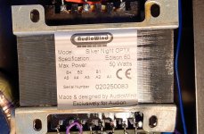
So the B1 on the transformer with the 2 blue wires coming from it are the + positive 8 ohm tap, the B4 with the green and purple wires are your -0 negative ohm tap.
You may also want to check the connection between A3 as there could be pieces of wire quite close to A4 that when powered up with nearly 500V could arc across and cause you problems.
Attachments
Last edited:
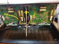
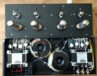
In 2019 I moved to Japan, so the amp needed reconfiguring to 100V. On that time I checked the insides for the first time, there was no signs of overheating, after two years of normal usage (3 hours daily in average). Here is how it looked on that time.
Attachments
Hi FB2017
The label on my OPTXs has A1-A5 and B1-B4 the other way round to yours (see photo). When I contacted the company they did say they had a batch that was incorrectly labelled, but said that the 8 and 4 ohm taps are the two closer together...this seems to be the situation you had. In my case the labelling is consistent with the instructions but - as I discovered recently when trying the 4 ohm tap and wondering why the output was so low - actually the 8 ohm tap is the one on the right. So it seems in my case that the transformers were actually assembled wrong...
Steve
Attachments
@steve7264 I too managed to turn it into an oscillator. Having sorted that it's kinda obvious how the cables are wired once they're correct!
Interesting that you were supplied with 10W resistors for R30, 31; I was supplied with 7W which quickly overheated and cracked.
@fb2017 I take on board your comments on poor soldering. I'm supposedly an experienced electronics engineer (I used to run a micro soldering company!), but founnd the wirewound resistors could be difficult to solder and had to burnish the leads for the solder to flow properly. So yes I hold my hands up to that one!
The output transformer labelling issue is very confusing. I've just checked mine and mine is the same as @fb2017.
@NickDP
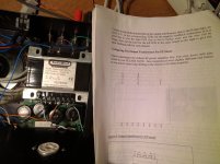
I just re-read your first post. I've just recently been making a few tweaks to mine including playing with the negative feedback - adding 330pF across the feedback resistor to get rid of some ringing in the square wave response.
When I did this I ended up with some quite buzzy hum from one speaker when the volume control was zero/low which disappeared when the volume control was higher. Sounds similar to what you are seeing? I connected my scope across the speaker terminals - and found it was oscillating at about 1.7MHz. Connecting a 10 ohm resistor and 100nF capacitor (in series) across each speaker to damp the oscillation seems to have cured this, and both channels are now very quiet at all volume settings.
Not sure if this is the best or only solution - maybe someone more expert will chip in - but you might want to try similar
@fb2017 I take on board your comments on poor soldering. I'm supposedly an experienced electronics engineer (I used to run a micro soldering company!), but founnd the wirewound resistors could be difficult to solder and had to burnish the leads for the solder to flow properly. So yes I hold my hands up to that one!
Wasn't meant to offend, as one doesn't know anything about the backgrounds of other people on this forum. I'm an EE myself, and I've fixed my builds sometimes simply by doing a quick reflow with a very hot iron at all soldering points. Still, I wonder why your 7W resistors burned, mine looked absolutely normal after two years of almost daily use. Something is still not right, have you left adequate space between them and other parts and did all the grid voltages, etc measured out correctly?
@steve7264 I also read about the noise issue. When I checked a while back I didn't see any HF oscillation on my scope as you describe.
Also I've never run run a square wave to check ringing so should do that.
I'm getting slight noise at zero vol from both channels but RH channel's slightly louder. No difference whether connected to a preamp or O/C inputs though I've not tried shorting the I/P's.
Turning up the vol control the noise in both channels decrease to zero with the control at the 10 O'clock position. Fortunately it's the ideal position for the control for normal listening.
Increasing the control beyond this point causes the noise in both channels to increase to a buzz that's becoming annoying, but it would be far too loud anyway at any level beyond about 11 O'clock!
I should really investigate it more as I'd like to use it at any volume control setting. Your comments are really helpful.
@fb2017 No offence taken at all and appreciate your comments! I've no idea why the resistors burnt as they did. I positioned them on long leads clear of the boards and to one side too.
I'll check the current through them by measuring the voltage across them to work out the power dissipated.
I have since made some quite fundamental mods to the whole amp which I'll document here when I work out how to post photos! It's interesting.....
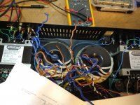
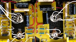
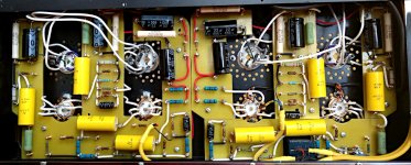
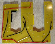
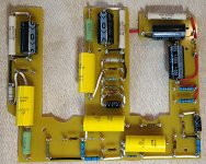
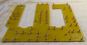
Lockdown has a lot to answer for, especially when I have too much time on my hands, and as a result I decided to rebuild my Edison by scrapping the PCB's and going for old school point to point wiring with tag boards.
I designed the tag board layouts, making sure there were as few crossed wires as possible, and that interconnects to the valves etc were as short as possible. The boards are 3mm G10 FR4 Fibreglass board from Ebay, and Glasshouse gold plated turret tags from hificollective, pressed in using my drill mounted in a stand as a makeshift press with the insertion tool in the drill chuck.
I cut the first LH channel board into 4 rectangles, and because it worked so well I used the pieces as a template for a single board for the second RH channel.
To make things more interesting I made the RH channel a mirror image of the left to make it visually more appealing. However it was quite challenging when it came to wiring everything up, as the valve holders had to be rotated around and I had to ensure all the connections went to the right places.
The advantage of the these turrets is wires can be inserted from underneath the board, which made for a much neater job on the top.
The valves are JJ E88CC’s and Genalex Gold Lion KT77’s which give a rich sound with plenty of bass.
The end result is…... it sounds exactly the same as the PCB version! But I’ve had a lot of fun doing it and especially how it looks visually. Ideally I’d redo the original LH channel as a single board, but I’m about to start building an Audio Creative DDAC 1794 so it will have to wait.
Issues I previously had with noise etc are still exactly the same, so the layout isn't the issue. I'll continue to look into this to get it as quiet as possible at all volume settings.
Attachments
-
 6 underneath detail1.jpg364.6 KB · Views: 133
 -
 5 complete underneath1.jpg286.2 KB · Views: 123
 -
 4 underwiring1.jpg535.9 KB · Views: 120
 -
 3 board components1.jpg495.2 KB · Views: 106
 -
 2 board turrets1.jpg268.1 KB · Views: 107
 -
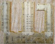 1 board layout2.jpg717.2 KB · Views: 166
 -
 7 top view1.jpg413.2 KB · Views: 133
- Status
- This old topic is closed. If you want to reopen this topic, contact a moderator using the "Report Post" button.
- Home
- Amplifiers
- Tubes / Valves
- Audion Edison 60 building and using report