Unix fan actually, spent many years in the world of SCO, well before they became a pariah. When something just works, without fanfare, real multitasking, on a machine that wouldn't have enough grunt these days to run a wristwatch,, you get tired of the Microsoft nonsense very quickly ...
Hi Mike,
This is just standard lag-lead compensation, and it does indeed work well. The MIC loop is compensated for a unity gain bandwidth of about 10 MHz.
Cheers,
Bob
100%agree!
And input stage itself is actually pretty slow. Most cases won't be stable at 10MHz.
Profound apologies to you bob, Bonsai and others! I have run the simulations with LTSPICE stock BJT models and have found the following:
1) Pole splitting does occur in fact with MIC, which is correctly so-named by Bob.
2) Only a fifth of the compensation capacitor used in ordinary Miller compensation may be used with MIC for the same loop transmission. I don't know at this stage why this is the case. Any ideas anyone?
3) MIC is NOT lead compensation at all, although it appears to produce a zero far beyond unity loop gain frequency that does not occur with ordinary Miller compensation.
4) The MIC local loop is unstable and requires compensation.
Now, why I obtained results in 2004 that suggested that MIC is lead compensation with the output stage excluded and did not cause pole splitting, I don't know at this stage; I must have made an elementary error with my simulations. Apologies to all.
Hi Mike,
Thank you very much for investigating this and sharing your conclusions with us.
You are exactly right regarding the need for compensation of the local MIC loop. The shunt lag-lead compensation across the LTP collectors I have used in the past was the best I could come up with at the time for the differential topology I was using. As mentioned above, it would be nice to come up with a more elegant way to compensate the MIC loop, such as with an embedded Miller loop. Not sure how to do that with the differential IPS/differential VAS topology I've been using, but there may be a way to do it with more common topologies.
As with other amplifiers I have designed with an EF-preceded VAS followed by an output Triple, sometimes a series R-C shunt to ground from the VAS output node is needed for best stability. In one case, I used values on the order of 100pF and 200 ohms in series for this shunt network.
Although SPICE has its limitations, over the years it has helped me countless times to gain insight into things that were non-intuitive to me, or which I simply did not understand.
Thanks again for looking into this and reporting your findings.
Cheers,
Bob
.... The shunt lag-lead compensation across the LTP collectors I have used in the past was the best I could come up with at the time for the differential topology I was using.
.....
Cheers,
Bob
Hi Bob,
I think this is the best you could do with your differential topology.
Out of curiosity I also simmed the MIC loop without shunt compensation: ULGF = 38MHz, PM = minus 86 dgr. and GM = minus 16dB. IOW, highly unstable and one definitely needs this shunt compensation.
Cheers,
E.
I recall seeing in sim some small diff pair "excess" feedback phase shift when the + input sees a high R - like a volume pot at midpoint
and that phase shfit improved with a small C to gnd on the + input - as could be excused as a RF input filter
hooking up the + input to spice Vsource with zero Z, or gnd could make this added diff pair phase contribution invisible in the sim
and that phase shfit improved with a small C to gnd on the + input - as could be excused as a RF input filter
hooking up the + input to spice Vsource with zero Z, or gnd could make this added diff pair phase contribution invisible in the sim
Last edited:
(above post deleted in the meantime)michaelkiwanuka said:.....
the shunt network doesn't improve stability margins in any way
....
Oh really?
see post 701 vs 704All you are saying Edmond is that the front end stage enclosed by the MIC needs to be compensated in addition to the global feedback loop.
Sounds pretty straight forward to me.
Hi Andrew,
Straight forward and obvious.
Cheers, E.
You are exactly right regarding the need for compensation of the local MIC loop. The shunt lag-lead compensation across the LTP collectors I have used in the past was the best I could come up with at the time for the differential topology I was using.
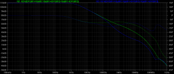
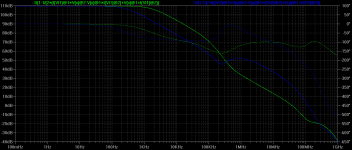
You're absolutely right. The shunt RC network adds a pole zero pair with the pole lowering the loop gain rapidly and the zero coming in before unity loop gain frequency to increase stability margins. Simulation is absolutely essential to fix the location of the pole and zero. Action of the pole-zero pair on minor loop gain response is shown below; phase shift at unity loop gain frequency is roughly -169 degrees with the RC network in situ and -254 degrees without it.
Bob, also note that only a fifth of the value of the compensation capacitor used with ordinary miller compensation may be used with MIC for the same loop gain. (do you know why this is the case?
 )
)This is excellent: slew rates are now comparable, potentially, with those obtainable with so-called "current feedback" arrangements.
We can now use "TMC" or TPC in a MIC configuration, I think (not tried it yet), to produce a potentially magnificent amplifier.
We now have to derive the agebraic expressions relating to the loop gain and the RC network to quantify the design process.
Attachments
Last edited:
Hi Andrew,
Straight forward and obvious.
Cheers, E.
Yes agree!
...
Out of curiosity I also simmed the MIC loop without shunt compensation: ULGF = 38MHz, PM = minus 86 dgr. and GM = minus 16dB. IOW, highly unstable and one definitely needs this shunt compensation.
Bob (and Andrew?) seem to have taken my point that the MIC loop needs some compensation but perhaps not this shunt compensation.
Ordinary Miller is better than shunt so nested (inner) Miller looks potentially better than an inner shunt.
The idea looks reasonable even if inapplicable to some (Bob's?) circuits.
Best wishes
David
MIC does facilitate very high slew rates because the it=CV limit associated with standard Miller comp is broken - you no longer have the integrator. Indeed, slew rate performance then approaches or equals that of CFA's.
The MIC loop will need compensation. You have a wide band LTP pair feeding a high gain voltage stage (I'll resist the temptation to call is a TIS ) with an HF pole due to Cob nestling inside a global FB loop. As Bob indicated earlier a ULGF of about 10 MHz for the MIC loop delivers good results.
The MIC loop will need compensation. You have a wide band LTP pair feeding a high gain voltage stage (I'll resist the temptation to call is a TIS ) with an HF pole due to Cob nestling inside a global FB loop. As Bob indicated earlier a ULGF of about 10 MHz for the MIC loop delivers good results.
Last edited:
(above post deleted in the meantime)
Oh really?
Yes, Edmond; I caught my silly mistake and deleted the post.
MIC does facilitate very high slew rates because the it=CV limit associated with standard Miller comp is broken - you no longer have the integrator. Indeed, slew rate performance then approaches or equals that of CFA's.
True.
 Nevertheless I suspect the MIC loop is still an integrator, although the input stage current no longer sets the limit on slew. I also contend that it is the second stage (TIS) current that limits slew with MIC.
Last edited:
The MIC loop will need compensation. You have a wide band LTP pair feeding a high gain voltage stage (I'll resist the temptation to call is a TIS ) with an HF pole due to Cob nestling inside a global FB loop. As Bob indicated earlier a ULGF of about 10 MHz for the MIC loop delivers good results.
This can probably be pushed even further. Typical LTP and small transistors have Ft around 100MHz. Some of the poles can be cancelled too, so I wonder where the limit is?
Best wishes
David
3) MIC is NOT lead compensation at all, although it appears to produce a zero far beyond unity loop gain frequency that does not occur with ordinary Miller compensation.
Hi Michael
I suspect that zero may be a product of the capacitor in parallel with the TIS emitter resistor, but I can't read the value from your picture. What is it?
It's not in Bob's schematic but I had planned to add this to cancel a pole. What was your reason to include it?
Best wishes
David
... why would you want to- just for a few more dB of loop...
A faster inner loop should leave you a bit more phase to play with in the outer loop. Obviously a bit of a balance and I would like to know where the limits are.
Best wishes
David
Hi Michael
I suspect that zero may be a product of the capacitor in parallel with the TIS emitter resistor, but I can't read the value from your picture. What is it?
Hi David,
No, the zero has nothing to do with the capacitor shunting the TIS's emitter resistor. The value of that capacitor is 1K, and is only there to prevent the resistor having any effect on loop transmission.
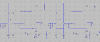
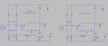
Ok, here is the minor loop simulation with TPC MIC compensated with shunt lag pole-zero network and ordinary TPC MIC without the pole-zero shunt compensation network.
The compensated TPC MIC gives phase shift of -119 degrees at unity loop gain, while the uncompensated TPC MIC minor loop gives a phase shift of -247 degrees at unity loop gain. The later is clearly unstable, while the former is very stable indeed.
It would appear TPC MIC with a compensated minor loop is a trully excellent idea indeed!
Attachments
Last edited:
- Status
- This old topic is closed. If you want to reopen this topic, contact a moderator using the "Report Post" button.
- Home
- Amplifiers
- Solid State
- Audio Power Amplifier Design book- Douglas Self wants your opinions