Unix fan actually, spent many years in the world of SCO, well before they became a pariah. When something just works, without fanfare, real multitasking, on a machine that wouldn't have enough grunt these days to run a wristwatch, ") , you get tired of the Microsoft nonsense very quickly ...
, you get tired of the Microsoft nonsense very quickly ...
, you get tired of the Microsoft nonsense very quickly ... some Windows don't allow direct access to program file folders - I wouldn't modify Lt libs anyway for compatibility
make a sim folder in your Documents - add models to a file like "mylib.lib" in the same folder, add .include "mylib.lib" to your asc
But I just want to modify my libs!

Windows 7 has got to be the worst thing that has ever happened to me-computationaly speaking!
But I just want to modify my libs!
Windows 7 has got to be the worst thing that has ever happened to me-computationaly speaking!
Right-click the folder, go to the security tab, add yourself to the list of trusted users, and done ...
But I just want to modify my libs!
Windows 7 has got to be the worst thing that has ever happened to me-computationaly speaking!
I quite like it, but then I laboured for years under Vista and Linux doesn't have the right software for my purposes. One thing that Vista taught me is not to install anything in the \Program Files directory. I put everything under \programs instead and this seems to work on W7 as well.
On the MIC topic, is it correct that the MIC loop needs to be unity gain stable? Leaving the need to compensate ~300 MHZ transistors for x1 instead of ~10 MHz for x30? Or is that too simplistic?
Hi Mike,
We'll all look forward to seeing the details of your simulation and how you have come to your conclusions from the results of the simulation.
You assert that:
1) MIC does not do any pole-splitting.
2) MIC is no different than lead compensation in the feedback loop.
Thanks for offering to do this.
Cheers,
Bob
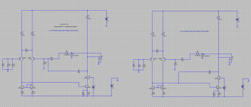
Profound apologies to you bob, Bonsai and others! I have run the simulations with LTSPICE stock BJT models and have found the following:
1) Pole splitting does occur in fact with MIC, which is correctly so-named by Bob.
2) Only a fifth of the compensation capacitor used in ordinary Miller compensation may be used with MIC for the same loop transmission. I don't know at this stage why this is the case. Any ideas anyone?
3) MIC is NOT lead compensation at all, although it appears to produce a zero far beyond unity loop gain frequency that does not occur with ordinary Miller compensation.
4) The MIC local loop is unstable and requires compensation.
Now, why I obtained results in 2004 that suggested that MIC is lead compensation with the output stage excluded and did not cause pole splitting, I don't know at this stage; I must have made an elementary error with my simulations. Apologies to all.
Attachments
Last edited:
FAS42,
Dual boot is the answer these days if you have the drive space and aren't crazy enough to use Windblows 8. Microsoft just messed me up for a couple of days with one of their critical updates. I installed it and then they say remove it as there is a problem. Uninstalled and then no way to start the computer. Couldn't repair the system, I had to reinstall and now all my good stuff is in the old windows file, damned if you do and damned if you don't. I've been playing with Linux for a long time and use Suse myself, but that just won't run my cad programs, they are all windows based and no way around that. I am looking at getting a new desktop but the new hardware crap that Microsoft has had so many manufacturers add to the bios system has me very wary of anything set up for Windows 8. I will never use that system and I think that Microsoft is getting the message that nobody wants that intrusive system that knows what is going on. My daughter has the only Apple system in the house and I won't touch their products, I have had to fix hers and have fixed others that are just not worth the bother.
michaelkiwanuka,
Glad you found you made a mistake and are man enough to admit that after all the arguing. Sometimes we just have to discover a problem ourselves before we can admit there is something that we just don't understand or didn't see.
2) Only a fifth of the compensation capacitor used in ordinary Miller compensation may be used with MIC for the same loop transmission. I don't know at this stage why this is the case. Any ideas anyone?
4) The MIC local loop is unstable and requires compensation.
Theses two point are linked , MIC loop has higher loop gain (hence the necessity of a lower cap) since the loop include the input stage that will add its gain but will introduce an additional pole due to the added ( of the same input stage) transfer function that is not present with
classical miller compensation(it is outside of this loop).
@Kindhornman
>Dual boot is the answer these days
Sure, or even triple boot. Eaybcd is the preferred S/W (even used by M$ itself!) for it.
> Microsoft just messed me up
Although I also have W8 (and XP) on my machine, I prefer W7. W8 is not mature enough and XP too slow.
As for backups, don't use MS stuff. Instead, use Macrium, it's reliable, fast and free.
Last but not least, keep all your data on a separate partition, including emails , bookmarks, history etc.
Cheers,
E.
Edmond,
I usually back up to an external drive with a mirror image so I can get back to where I was when there is a problem, but alas I have been lazy lately and hadn't done that. I didn't lose anything, as the new installation just made a partition and put everything old into that partition but that is a pain in the rear to say the least. I converted from XP to Windows 7 and find it easy to use and I am glad I skipped the Vista as I have used it and hated it every time I had to deal with the question do you really want to do this over and over! Now I get to drag everything I want into the new partition, I will be getting my external drive back out and keeping my backups on that. I have a second internal drive but the problem is that if the bios is messed up you can't get to the second drive if it is internal. Sometimes we just get lazy or forget the hassles until it happens and then we have to remember why we did that in the first place.
What is eaybcd by the way?
Steven
Hi Steven,
>What is eaybcd by the way?
Sorry for the typo, I mean: Easybcd, see: EasyBCD - NeoSmart Technologies
Cheers,
E.
>What is eaybcd by the way?
Sorry for the typo, I mean: Easybcd, see: EasyBCD - NeoSmart Technologies
Cheers,
E.
Mikeks, yes the MIC loop will probably require compensation.....Usually an RC combo across the LTP collector load is the best place to implement this.
It would appear placing shunt capacitance across the current mirror output introduces a pole in the local loop that worsens the instability of the local loop.

Adding a resistor in series with the shunt capacitance merely cancels that pole with a zero, which gets you right back where you started.
Last edited:
...
2) Only a fifth of the compensation capacitor used in ordinary Miller compensation may be used with MIC for the same loop transmission. I don't know at this stage why this is the case. Any ideas anyone?
...
Michael,
Thats why I lowered to the feedback resistors as they are part of the integrator with MIC, as well as encompassing more gain.
Glad to see you got past the software install problems.
edit: For your loop gain, given the ideal buffer stage you don't need the current injection at that node. Neat thing about LTspice is after the dual run you can still plot just the voltage across the vsource for the voltage run or the voltage with the current source only, for a comparison to the dual source, or to see the individual contributions (just use plot setting-select steps or the @1, @2 selections).
Good Luck
-Antonio
Last edited:
... I have run the simulations with LTSPICE stock BJT models and have found the following:...
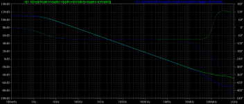
The MIC local loop is unstable and requires compensation.
Nice work and informative. Well done all-round.
I assume the Green plot is the MIC? The global phase looks better than one could hope!
Mikeks, yes the MIC loop will probably require compensation. Bob has mentioned this a few times. Usually an RC combo across the LTP collector load is the best place to implement this.
Why do you think this? Prima facie I would expect the best way would be to have a little nested Miller compensation around the VAS itself. I previously asked Bob about this and he replied that he did the shunt load because it was simple when he already had a lot of innovation to work out.
Best wishes
David
2) Only a fifth of the compensation capacitor used in ordinary Miller compensation may be used with MIC for the same loop transmission. I don't know at this stage why this is the case. Any ideas anyone?
Michael,
Thats why I lowered to the feedback resistors as they are part of the integrator with MIC, as well as encompassing more gain.
It's a function of the resistor values. For the usual Miller compensation, the ULGF is gm1*B/Cm. gm1 is the LTP transconductance; B is the feedback ratio which I have taken as approximately R7/R8? (can't read it) for closed loop gain >>1.
For the MIC, the ULGF is 1/(Cm*R14). R14 and R8 are the same resistor in the two circuits so can cancel out in the algebra.
For equal Cm in both cases, the result is 1/gm1 ~= R7. Since your 1/gm1 is about one-fifth of your R7, you need a 5x capacitor.
It would appear placing shunt capacitance across the current mirror output introduces a pole in the local loop that worsens the instability of the local loop.
Adding a resistor in series with the shunt capacitance merely cancels that pole with a zero, which gets you right back where you started.
Hi Mike,
This is just standard lag-lead compensation, and it does indeed work well. The MIC loop is compensated for a unity gain bandwidth of about 10 MHz.
Cheers,
Bob
- Status
- This old topic is closed. If you want to reopen this topic, contact a moderator using the "Report Post" button.
- Home
- Amplifiers
- Solid State
- Audio Power Amplifier Design book- Douglas Self wants your opinions