...
I have run major loop gain simulations of an ordinary Miller compensated amp., and then merely connected the end of the compensation capacitor connected to the input of the second stage to the inverting input of the amp and run the simulation again.
The results demonstrate that pole splitting does not occur with your "MIC". Period. ...
Micheal, your results seem very different than what I would expect, namely to require even less compensation capacitance back to the inverting input acounting for the added gain as well as to "pole split" the added phase (presuming the feedback resistance is accounted for).
Any chance you can link the simulation results?
Thanks
-Antonio
I am not sure I understand. 
Nevertheless, I run the simulations several years ago and haven't got the results to hand.
However, you should have no difficulty running them on a Douglas Self type amplifier in LTSPICE. Just use the loop gain probe to plot the major loop gain response for each circuit iteration.
Nevertheless, I run the simulations several years ago and haven't got the results to hand.
However, you should have no difficulty running them on a Douglas Self type amplifier in LTSPICE. Just use the loop gain probe to plot the major loop gain response for each circuit iteration.
Well, he really shouldn't have bothered "reinventing" the wretched things, and he really ought not to have misled millions of engineers thereafter by incorrectly renaming them "CFAs".
We definately need an axe grinding smilie.
...
However, you should have no difficulty running them on a Douglas Self type amplifier in LTSPICE. Just use the loop gain probe to plot the major loop gain response for each circuit iteration.
Micheal,
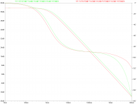
I take it this is not what you are taking about?
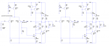
I've kept the compensation capacitor the same and adjusted the feedback resistors equivalent resistance to give nearly equal loop gain.
Green is around the vas, red is returned to negative input.
Circuit was borrowed from Bob Cordell's web site (and it should be close to original form), thanks.
Thanks
-Antonio
Attachments
Last edited:
We definately need an axe grinding smilie.
I think the millions is an exaggeration like much of the other hubris.
I've kept the compensation capacitor the same and adjusted the feedback resistors equivalent resistance to give nearly equal loop gain.
Cascode the second stage so that its base-collector intrinsic capacitor does not affect the results. Also, shunt the input to ground with a large cap., viz. eliminate the voltage sources at the input, and do not alter the feedback resistors from one iteration to the next. Loading the output is not really necessary in this case. Make sure it is the major loop gain you are simulating in fact.
Last edited:
We definately need an axe grinding smilie.
I can think of one or two more that would be even more appropriate.
...
no one I've seen anywhere I've worked as an engineer even gets up to Cherry's JAES audio amplifier modeling articles' admittance matrix level of analysis
almost all detail is thrown out to limit complexity to what little humans can handle...
Isn't Cherry's admittance matrix essentially just what Bode used in 1940-5?
I am somewhat reassured that few other people work at that level because I certainly find it an effort. My current project is an attempt at a Middlebrook style "low entropy" version of admittance matrix analysis, have you considered this or are you aware of any work in that direction?
Best wishes
David
Simulation used a compensation capacitor of 100pF but can add the cascode or remove the parasitic capacitance if you really think its a significant detail.Cascode the second stage so that its base-collector intrinsic capacitor does not affect the results.
You want me to replace ideal sources with a large cap ?Also, shunt the input to ground with a large cap., viz. eliminate the voltage sources at the input.
I didnt, both circuits have the same resistors. I set the values to have both loops nearly equal, with input compensation the feedback resistors set the crossover frequency (no loading intended).do not alter the feedback resistors from one iteration to the next. Loading the output is not really necessary in this case.
Likely the issue of miscommunication, where exactly would you like me to measure your major loop (and with what conditions left on the global loop)?Make sure it is the major loop gain you are simulating in fact.
Thanks
-Antonio
More like "grinding the wrong end of a screwdriver" in this case.axe grinding
That would be much appreciated.To save time and to leave no room for error, I will have to re-run the simulations myself when I find the time and post the results.
Anyone enlighten me on what and how to incorporate a "loop gain probe" in LTspice?
Please don't ask me to Google Middlebrook or Tian cos I have and have no idea how to use this to measure "loop gain" in a practical amp simulation.
PS I have used Cherry's matrix analysis and YES, it brings new insights into what's happening .. especially if you have a difficult 'parasitic' instability case. In dem days I cud reed, rite en ****
")
...
Anyone enlighten me on what and how to incorporate a "loop gain probe" in LTspice?
There are examples in LoopGain.asc (Middlebrook) and LoopGain2.asc (Tian) in the LTSpice libraries provided. They contain instructions. Don't be confused by the different ways that the two probes are implemented, this is not related to the difference between Middlebrook and Tian's formulations
Best wishes
David
the "simple Middelbrook" probe is just a single Vsource with AC 1 value in series with feedback at a "loop breaking point"
the loop gain is calculated as the ratio of the two V on either side
placing it at a spot that has low Z on one side, much higer Z on the other gives quite adequate accuracy in most cases
the more complex Tian/Middelbrook LoopGainProbe uses a additional current test source, rather complicated equation evaluated with a stepped simulation that excites the circuit with each source independently
the additional complexity correctly acounts for "bidirectional" signal flow/loading effects
the "simple Middelbrook" probe is just a single Vsource with AC 1 value in series with feedback at a "loop breaking point"
the loop gain is calculated as the ratio of the two V on either side
placing it at a spot that has low Z on one side, much higer Z on the other gives quite adequate accuracy in most cases
the more complex Tian/Middelbrook LoopGainProbe uses a additional current test source, rather complicated equation evaluated with a stepped simulation that excites the circuit with each source independently
the additional complexity correctly acounts for "bidirectional" signal flow/loading effects
The Middlebrook 1975 article actually has 3 (or 4) probes in it so it is a bit debatable which is "the" Middlebrook probe.
First he reviews the simple V source (or current source dual) you mention above.
Secondly he discusses consecutive potential and current injection and the way to combine the results. This is the method used in LoopGain.asc. It accounts for finite impedance load effects at the injection point.
Finally he presents his invention of consecutive potential and current null injection. This technique reduces sensitivity to experimental errors but seems unnecessary in a simulator. It is the technique that Tian et al build upon and also appears to be Middlebrook's first publication on null injection techniques. It deserves his name but since it is rarely used perhaps the honour should descend to the second technique. It is only the Tian probe that accounts for bidirectional flow effects.
Best wishes
David
PS. The Null double injection is rarely used in audio. More common in RF/microwave experimental work I expect.
PSS Tian et al also use "Middlebrook" to refer to the double injection technique and not the V source.
Last edited:
Sounds like a typical Windows "stupidity" - most everyone has to deal with this brain-dead operating system ... you just learn to curse a bit, and move on ...Jcx,
I am trying to install third party models into the lib of a new LTSPICE installation but every time I try to save the edited lib an "access denied" message pops up. Any ideas?
To save time and to leave no room for error, I will have to re-run the simulations myself when I find the time and post the results.
Hi Mike,
We'll all look forward to seeing the details of your simulation and how you have come to your conclusions from the results of the simulation.
You assert that:
1) MIC does not do any pole-splitting.
2) MIC is no different than lead compensation in the feedback loop.
Thanks for offering to do this.
Cheers,
Bob
Sounds like a typical Windows "stupidity" - most everyone has to deal with this brain-dead operating system ... you just learn to curse a bit, and move on ...
Just install 'TakeOwnershipEx' and the 'stupidity' is gone (at least this one).
BTW, you sound like a true Linux fan, right?
Cheers,
E.
- Status
- This old topic is closed. If you want to reopen this topic, contact a moderator using the "Report Post" button.
- Home
- Amplifiers
- Solid State
- Audio Power Amplifier Design book- Douglas Self wants your opinions