No worries. You don't need 2 other 3.3V. I just wanted to optimise and take advantage of the Group Buy, so I decided I might as well add power and SuperCaps to the TransportPi. You only need 1 other 3.3V. Power to the TransportPi is optional as it gets power via GPIO by default.
I believe the other 3.3V (StationPi J5) is needed to power the GPIO of the Audio HAT's. Without the StationPi (Traditional Way), feeding 5V into the FifoPi helped power the GPIO. With the StationPi (Modern Way), something has to help power the GPIO now that the power is separated from the RPi power. The clean power on the FiFoPi J5 3.3V is mainly dedicated to power the clocks? So how do the Audio HAT GPIO's get power... How is the TransportPi going to get power? Not through the clean power FiFoPi J5 3.3V or isolated RPi StationPi J3 5V...
It looks to be a trend with Ian's products migrating more to 3.3V so one can bypass the LDO. Now instead of relying on having to use 5V so the RPi can get power via the FiFoPi 5V, one can just power the FiFoPi -> GPIO -> TransportPi with 3.3V directly via the StationPi J5. Could be completely wrong. Just IMO. Again, anyone please correct if I'm wrong. I'm here to learn and try to do things the proper way to achieve MAX SQ.
I'm new to this hobby and have not unsealed my StationPi yet, so have zero experience in the matter ATM. Ian maybe still recovering from the massive GB, so you may want to check out the discussion here in the meantime:
https://www.diyaudio.com/forums/dig...mate-weapon-fight-jitter-574.html#post6415640
Finally got it all worked out. Ideally I need 2x 5v supply for PI and for gpio pins on clean side (J3 and J5) and one 3.3v supply direct to the Fifopi Q3( feeding Q3 and transport pi.
@ozcal.
Beautiful. Glad it worked out M8.
I love the flexibility of these Ian Canada products.
Initially, I was planning 2x 5v + 1x 3.3v before the StationPi official launch, but once I went pure battery solution it opened the doors for 1x 5v + 2x 3.3v.
Either way, it's going to sound solid.
Beautiful. Glad it worked out M8.
I love the flexibility of these Ian Canada products.
Initially, I was planning 2x 5v + 1x 3.3v before the StationPi official launch, but once I went pure battery solution it opened the doors for 1x 5v + 2x 3.3v.
Either way, it's going to sound solid.
I can confirm that this combination works and sounds very well ")
@ozcal.
Beautiful. Glad it worked out M8.
I love the flexibility of these Ian Canada products.
Initially, I was planning 2x 5v + 1x 3.3v before the StationPi official launch, but once I went pure battery solution it opened the doors for 1x 5v + 2x 3.3v.
Either way, it's going to sound solid.
I can confirm that this combination works and sounds very well
Noted. In case someone in the future may have similar requirements will quote @holco:
5V is Powered via stationpi, output is from Linear power supply Supported By supercaps going into FiFo via GPIO
Wallmount Raspberry powersupply (5V) is used to feed J3 on stationpi, recommended by Ian in stationpi manual and in this way completly isolated from 5V clean side.
First 3.3V battery supply with super caps is powering FiFo clean side.
Second 3.3V battery supply with super caps is powering transportpi with onboard ldo bypassed, IN/OUT is bridged by wire.
Ground question need some help
I need help figuring out how to ground my I2S streamer that I am building with Ian's parts.
Hoping someone or Ian can advise
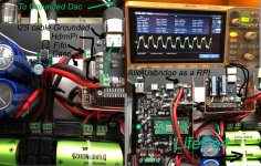
I attached a photo collage of my system.
HdmiPi, Fifo 3, Allo Usbridge as RPI ,LifePo4, I2s Cable to my Dac
When I Attach the I2S Cable that is connected to City ground via the Dac it automatically connect to the Battery negative of the HDMIPI and introduce a 60Hz ripple on the battery line (I do not hear any noise) but I am concerned as we went to a great deal using Ian's amazing parts to have a ripple free power.
Big Questions:
1) Should all the battery negatives connect to the Chassis and ground the Chassis. that could be good and bad
2) Cut the I2S grounded Shield close to the entry, it will still be shielded but not connecting to the battery negative of my streamer.
3) What battery negatives should connect together, which of them should connect to City ground and how to eliminate ground noise.
I need help figuring out how to ground my I2S streamer that I am building with Ian's parts.
Hoping someone or Ian can advise
I attached a photo collage of my system.
HdmiPi, Fifo 3, Allo Usbridge as RPI ,LifePo4, I2s Cable to my Dac
When I Attach the I2S Cable that is connected to City ground via the Dac it automatically connect to the Battery negative of the HDMIPI and introduce a 60Hz ripple on the battery line (I do not hear any noise) but I am concerned as we went to a great deal using Ian's amazing parts to have a ripple free power.
Big Questions:
1) Should all the battery negatives connect to the Chassis and ground the Chassis. that could be good and bad
2) Cut the I2S grounded Shield close to the entry, it will still be shielded but not connecting to the battery negative of my streamer.
3) What battery negatives should connect together, which of them should connect to City ground and how to eliminate ground noise.
Attachments
Don't forget to remove L1 from the TransportPi.
Noted. In case someone in the future may have similar requirements will quote @holco:
I need help figuring out how to ground my I2S streamer that I am building with Ian's parts.
Is your scope grounded too?
I need help figuring out how to ground my I2S streamer that I am building with Ian's parts.
Is your scope grounded too?
It was grounded with a tip and barrel method, but you brought my attention to something.
I plugged the scope in the same outlet as the Dac eliminating all other connections more like a star grounding the noise dropped significantly to 2mv. bringing a separate ground from the same source to the hats negative poles dropped it down further to 1mv.
* But still should I let City ground connect to the hats negative poles?
Don't forget to remove L1 from the TransportPi.
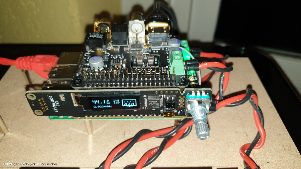
Thanks for the heads up. I noticed this step in the manual but I could never locate "L1" on the PCB Layout (top) within the manual. I have not physically looked under the TransportPi yet (bottom).
Is "L1" basically that small board in the middle of the TransportPi with the labels "3.3V REG" and "LOW NOISE"?
If so, do I just solder a wire to "IN" on one end and "OUT" on the other end?
EDIT: I noticed in your photo the wiring on the TransportPi. Is this the step to remove "L1"?
Manual
If you want to use an independent DC power supply for TransportPi, you will need:
- Solder the supplied DC terminal connector to the position of J3.
- Remove FB L1 at bottom side of PCB if you don’t want this power supply connected to GPIO anymore.
- Feed good 5V linear/ultra capacitor voltage rail or 3.3V LifePO4/ultra capacitor rail to J3.
- If 3.3V pure LifePO4 or ultra capacitor voltage is used, it’s highly recommended to bypass the on-board low
noise LDO by soldering jumper wires between IN and OUT as described above.
Last edited:
Don't forget to remove L1 from the TransportPi.
I have a transportPI that I swapped with HdmiPI as I did not want the unneeded extra circuitry so I was able to take a nice photo L1 is on the back close to the input voltage
Attachments
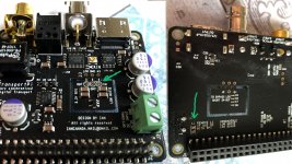
I have a transportPI that I swapped with HdmiPI as I did not want the unneeded extra circuitry so I was able to take a nice photo L1 is on the back close to the input voltage
Thank you for taking the time to take a photo.
I always wondered where the "L1" was located...
I will not start this process until a ReclockPi is in hand when I have to purchase my 2nd TransportPi.
My 1st TransportPi will be left un-modded.
Look at b and d.
If you want to use an independent DC power supply for TransportPi, you will need:
a. Solder the supplied DC terminal connector to the position of J3.
b. Remove FB L1 at bottom side of PCB if you don’t want this power supply connected to GPIO anymore.
c. Feed good 5V linear/ultra capacitor voltage rail or 3.3V LifePO4/ultra capacitor rail to J3.
d. If 3.3V pure LifePO4 or ultra capacitor voltage is used, it’s highly recommended to bypass the on-board low
noise LDO by soldering jumper wires between IN and OUT as described above
Thanks for the heads up. I noticed this step in the manual but I could never locate "L1" on the PCB Layout (top) within the manual. I have not physically looked under the TransportPi yet (bottom).
Is "L1" basically that small board in the middle of the TransportPi with the labels "3.3V REG" and "LOW NOISE"?
If so, do I just solder a wire to "IN" on one end and "OUT" on the other end?
EDIT: I noticed in your photo the wiring on the TransportPi. Is this the step to remove "L1"?
Manual
Last edited:
* But still should I let City ground connect to the hats negative poles?
I would suggest to make it optional. IME it can help, hurt, or make no difference. Have to try it under the conditions where the equipment will be used to see.
Look at b and d.
b. Remove FB L1 at bottom side of PCB if you don’t want this power supply connected to GPIO anymore.
d. If 3.3V pure LifePO4 or ultra capacitor voltage is used, it’s highly recommended to bypass the on-board low
noise LDO by soldering jumper wires between IN and OUT as described above
d. seems pretty straightforward. just need to solder a single jumper wire on two ends.
b. unsure how to remove. can I just pull out the metal piece off of L1? do I need to de-solder?
Note: I cannot proceed ATM because I need to purchase a second TransportPi. My current TransportPi is in production un-modified, so I don't want to touch since STABLE. But this will really be beneficial once I get the second TransportPi.
Last edited:
L1 must of course be desoldered.
d. seems pretty straightforward. just need to solder a single jumper wire on two ends.
b. unsure how to remove. can I just pull out the metal piece off of L1? do I need to de-solder?
Note: I cannot proceed ATM because I need to purchase a second TransportPi. My current TransportPi is in production un-modified, so I don't want to touch since STABLE. But this will really be beneficial once I get the second TransportPi.
L1 must of course be desoldered.
Cheers for the confirmation.
I likely will not be able to attempt this feat until the Summer, so it's great to know the proper step in advance.
Not comparable to how it sounds in real live, but it gives an idea
Recorded with a Tascam DR-40 (48kHz)
Raspian (Ian Canada) streamer
Audio-GD R8 (2021) DAC
Audio-GD Master 1 Vacuum XLR preamplifier
Mordaunt Short Performance 6 Limited Edition loudspeakers (converted to full active with 6x NCore poweramp's (Two Hypex FusionAmp's FA253)
Freya Redings - Lost Without You - YouTube
Simply Red - So Beautiful - YouTube
Cigarettes After Sex - Apocalypse - YouTube
Patrick Watson - Lighthouse - YouTube
Beautiful sound and system thanks for sharingNot comparable to how it sounds in real live, but it gives an idea
- Home
- Source & Line
- Digital Line Level
- Asynchronous I2S FIFO project, an ultimate weapon to fight the jitter