Ian ... Just as a reference, what are you using to power the FIFO and Clock Board?
SD
@sidny
I use Salas 5V Reflektor-D powering FIFO.
I use one cell of LifePo4 battery powering Dual XO.
There is an isolator between my FIFO and clock board.
Good weekend.
Ian
Ian, do you have a RPI connector board left ?
JG
@ Giordano
I still have a couple of them left. Please PM me your shipping address if you need it.
Good weekend.
Ian
Do you still have another RPi adapter board left, Ian?
I would love to test RPi with runeaudio and see how it compares to my current setup that uses wandboard with LMS.
Many thanks!!!
@Alcaudon
Only one left, please PM me your shipping address if your want it
") .
.Regards
Ian
@Alcaudon
Only one left, please PM me your shipping address if your want it
Regards
Ian
PM sent, many thanks for everything Ian!!!
Hi analog_sa,
FIFO works as a clock isolator. Theoretically, if data keeps no change,anything before FIFO will not affect any to the sound quality . However, in the real world, jitter can still be introduced from something else, such as ground or EMC noise from air(even you have an isolator), but should be much less than directly introduced from original audio clock.
I involved in medical equipment industry for many years. To get FDA certification, each new produce we developed have to pass EMC class B. So I often go to EMC testing labs. You can see everything on the screen of a spectrum analyzer. Your system clock, PLL, switching power supply, DDR memory, BUS, USB, TFT and anything else. Each of those EMC sources are located at different peak point of the spectrum. If we change the firmware, some of peak points will also be changed. All of them were picked up from an antenna in a shield chamber 3 to 5 maters away from our product. Especially the frequency range from 100MHz to 700MHz, very difficult to be suppressed.
That's why sometimes a shield works for a clock board or DAC.
If we put it that way, what your were saying, I think, is really reasonable.
Regards,
Ian
I reintroduce the topic....
She would be the best location for a Raspberry,inside DAC enclosure with insulating case,or outside DAC with cables of about ten centimeters
Dear Ian,
Let me first say that I’m impressed how you have taken this concept of a FIFO as jitter killer and turned it into reality. And you keep on optimizing and improving it and providing it as high quality modules to the DIY community. Excellent stuff and thanks for all the efforts you put in!
I’ve been following this thread for a long time now and it is one of my favourite here on DIYAudio. And for quite some time I have been thinking about how I could best use it to improve the quality of my audio system. I think I’ve found the ideal application for me: as part of an audio streamer.
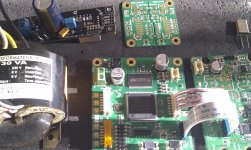
This is what the hardware of the streamer should look like:
RPi > I2S FIFOII > Dual XO II > SPDIF
I want to play into the DAC section of my dCS Puccini CD player using SPDIF.
Now I have two questions:
Your input on this would be much appreciated!
I can imagine that more people would like to build a streamer like this as frontend for an existing DAC. Maybe someone on this forum already has experience with this?
Kind regards,
Albert Jochems
Let me first say that I’m impressed how you have taken this concept of a FIFO as jitter killer and turned it into reality. And you keep on optimizing and improving it and providing it as high quality modules to the DIY community. Excellent stuff and thanks for all the efforts you put in!
I’ve been following this thread for a long time now and it is one of my favourite here on DIYAudio. And for quite some time I have been thinking about how I could best use it to improve the quality of my audio system. I think I’ve found the ideal application for me: as part of an audio streamer.
This is what the hardware of the streamer should look like:
RPi > I2S FIFOII > Dual XO II > SPDIF
I want to play into the DAC section of my dCS Puccini CD player using SPDIF.
Now I have two questions:
- This setup (I2S FIFO into SPDIF) is the only one you do not describe in the manual of the SPDIF Interface Board. I know that SPDIF is a less than perfect connection option, but I’m not willing to hack my Puccini (yet) to feed directly into the I2S path. And I have the option to sync using a Wordclock (see next question) I’m not a specialist but from the DIX9211 datasheet it seems that it uses a PLL to generate the clock for the SPDIF signal generation. You write in the manual that you use a re-clock circuit to reduce transmission jitter. May I assume that the clock for this is derived from the Dual XO board and therefore benefits from the quality clocks in there?
- My Puccini accepts Wordclock signals (as commonly used in pro-audio equipment) and some experiments (e.g. with a Puccini Scarlatti clock and a Mutec MC3) have shown me that the internal clock of the Puccini can still be improved upon. I would like to use the WS clock of the unused I2S output on the Dual XO board. Now the Wordclock standard is 75Ohm/BNC and you use 50Ohm for the I2S connections throughout your modules. How can I best go about this? Is the output of the board able to drive a longer cable and should I just replace the termination resistor on that output (and can you point me to that one)? Or should I use an additional buffer, and do you have a suggestion for that?
Your input on this would be much appreciated!
I can imagine that more people would like to build a streamer like this as frontend for an existing DAC. Maybe someone on this forum already has experience with this?
Kind regards,
Albert Jochems
Dear Ian,
Let me first say that I’m impressed how you have taken this concept of a FIFO as jitter killer and turned it into reality. And you keep on optimizing and improving it and providing it as high quality modules to the DIY community. Excellent stuff and thanks for all the efforts you put in!
I’ve been following this thread for a long time now and it is one of my favourite here on DIYAudio. And for quite some time I have been thinking about how I could best use it to improve the quality of my audio system. I think I’ve found the ideal application for me: as part of an audio streamer.
This is what the hardware of the streamer should look like:
RPi > I2S FIFOII > Dual XO II > SPDIF
I want to play into the DAC section of my dCS Puccini CD player using SPDIF.
Now I have two questions:
- This setup (I2S FIFO into SPDIF) is the only one you do not describe in the manual of the SPDIF Interface Board. I know that SPDIF is a less than perfect connection option, but I’m not willing to hack my Puccini (yet) to feed directly into the I2S path. And I have the option to sync using a Wordclock (see next question) I’m not a specialist but from the DIX9211 datasheet it seems that it uses a PLL to generate the clock for the SPDIF signal generation. You write in the manual that you use a re-clock circuit to reduce transmission jitter. May I assume that the clock for this is derived from the Dual XO board and therefore benefits from the quality clocks in there?
- My Puccini accepts Wordclock signals (as commonly used in pro-audio equipment) and some experiments (e.g. with a Puccini Scarlatti clock and a Mutec MC3) have shown me that the internal clock of the Puccini can still be improved upon. I would like to use the WS clock of the unused I2S output on the Dual XO board. Now the Wordclock standard is 75Ohm/BNC and you use 50Ohm for the I2S connections throughout your modules. How can I best go about this? Is the output of the board able to drive a longer cable and should I just replace the termination resistor on that output (and can you point me to that one)? Or should I use an additional buffer, and do you have a suggestion for that?
Your input on this would be much appreciated!
I can imagine that more people would like to build a streamer like this as frontend for an existing DAC. Maybe someone on this forum already has experience with this?
Kind regards,
Albert Jochems
Hi Albert,
Thank you for your question.
1. S/PDIF signal will benefit from FIFO. It will be driven by clock from Dual XO but from DIX9211. So, the sound quality will be improved with FIFO being placed into system.
2. To drive a 75ohm cable, you need replace the 33ohm source impedance matching resistor with a 50ohm one for the corresponding u.fl MCLK output socket. And also you need to confirm your clock receiver works with 3.3V LVTTL logic level.
I'll be out of town for whole week next week. If your have more questions, I'll get back to you after that.
Have a good weekend.
Ian
Ian - as a followup on the FIFO and Clock Board power question.
What powers your RPI, if I may ask?
Hi xaled,
You can use any kind of power supply for PPI if you have an isolator before clock board.
Regards,
Ian
Hi Albert,
Thank you for your question.
1. S/PDIF signal will benefit from FIFO. It will be driven by clock from Dual XO but from DIX9211. So, the sound quality will be improved with FIFO being placed into system.
2. To drive a 75ohm cable, you need replace the 33ohm source impedance matching resistor with a 50ohm one for the corresponding u.fl MCLK output socket. And also you need to confirm your clock receiver works with 3.3V LVTTL logic level.
I'll be out of town for whole week next week. If your have more questions, I'll get back to you after that.
Have a good weekend.
Ian
Dear Ian,
Thanks for your response.
It sounds like it is worth it to start this experiment. I'll first order the boards that I need and will come back with some practical questions afterwards!
Albert
Dual leads Crystal
Hello Ian,
I need some help please :
I'm using the FIFO 2 and Clock 2 boards without isolation between them.
Is it the FFC/FPC flat cable which is providing the power supply to the Clock 2 board ?
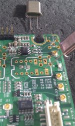
Can I use a two leads XO ? You said you tried the Laptechs from Andrea, but can you show me please which are the holes used : too much holes for a non dip XO ! The gap between the leads is shorter than the width of the gap in the pcb (I have the pcb without the dip8 connectors).
Can I use later between the two boards the non populated isolator (the simpliest one you provided with the first I2S to PCM bords) ? Or do I go with the populated isolator sold in the list ?
Thank you very much for your help,
best regards
Hello Ian,
I need some help please :
I'm using the FIFO 2 and Clock 2 boards without isolation between them.
Is it the FFC/FPC flat cable which is providing the power supply to the Clock 2 board ?
Can I use a two leads XO ? You said you tried the Laptechs from Andrea, but can you show me please which are the holes used : too much holes
for a non dip XO ! The gap between the leads is shorter than the width of the gap in the pcb (I have the pcb without the dip8 connectors).Can I use later between the two boards the non populated isolator (the simpliest one you provided with the first I2S to PCM bords) ? Or do I go with the populated isolator sold in the list ?
Thank you very much for your help,
best regards
Well lets se what Ian says. Manual says:
Two sockets for XOs: U1 and U2
Both sockets must be installed with proper XO. Standard DIP 3.3V clock oscillators with 14- or 8- pin configurations are available for U1 and U2. SMT oscillators are also available for Dual XO II with sockets non-populated (model B). For external XOs, two reserved SMA RF connectors can be used.
External need still to be 3,3V I suppose.
Andreas crystals (NB: Not oscillators - an oscillator contains a crystal!) are not electrical compatible. It's Andreas board that makes it an oscillator/clock.
//
- Home
- Source & Line
- Digital Line Level
- Asynchronous I2S FIFO project, an ultimate weapon to fight the jitter