Andrew's Grundig DEM Done!!
Holly S**t!!
This is not a subtle improvement. I only had 15 minutes to listen but the verdict is already in. The 200pf cap was big. This is massive. I'll write more about the sound after a few days of listening.. Its almost hard to describe. Dark dark background. Every instrument, every note stands alone and distinct in space. Yet it is all coherent. everything is tight and yet easy at the same time. Natural. Symbols were good, but now great.
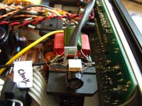
Technically I followed the Grundig circuit Andrew found. My execution with a soldering iron sucks, but I went for some tight fits. Put 200nf film caps right on pins 16 & 17 on the back side of the PCB. Used parts on hand. The caps werre pulled from the ARCAM board when I upgraded the first of the 14 decoupling caps. Would have liked to have had the surface mounted solid polymer caps ECDEsigns recommends, but could not wait for a parts shipment. Used a 2k7 Ritken from the parts bin instead of the 2k2 recommended. Seems fine. Added a pretty massive inductor on the -15v feed prior to the DEM circuit. ECDesigns advised that this would prevent noise from DEM oscillator getting back into rest of supply. I'll never know if this was good because I will not be touching this for a long time. The sound is quite fine.
Gents, this is awesome! It will only get better as it settles.
Holly S**t!!
This is not a subtle improvement. I only had 15 minutes to listen but the verdict is already in. The 200pf cap was big. This is massive. I'll write more about the sound after a few days of listening.. Its almost hard to describe. Dark dark background. Every instrument, every note stands alone and distinct in space. Yet it is all coherent. everything is tight and yet easy at the same time. Natural. Symbols were good, but now great.
Technically I followed the Grundig circuit Andrew found. My execution with a soldering iron sucks, but I went for some tight fits. Put 200nf film caps right on pins 16 & 17 on the back side of the PCB. Used parts on hand. The caps werre pulled from the ARCAM board when I upgraded the first of the 14 decoupling caps. Would have liked to have had the surface mounted solid polymer caps ECDEsigns recommends, but could not wait for a parts shipment. Used a 2k7 Ritken from the parts bin instead of the 2k2 recommended. Seems fine. Added a pretty massive inductor on the -15v feed prior to the DEM circuit. ECDesigns advised that this would prevent noise from DEM oscillator getting back into rest of supply. I'll never know if this was good because I will not be touching this for a long time. The sound is quite fine.
Gents, this is awesome! It will only get better as it settles.

Oh dear, when I turn my CD player on it kills the radio in the kitchen DEAD. Not even just interference such as when a laptop is running off the mains in the room but total silence from the radio. If the external supplies are unplugged it doesn't happen so it's something to do with them - the unshielded wires to the Arcam or the incomplete metal chassis, or both. I could do with fixing this as the RFI leakage is only going to harm sound quality.
Hi Martin,
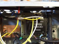
Yes, the PSU box is full of DC. I've now isolated the cause of the radio interference. After a little chat with Brent he asked about the clock supplies and I went from there and found the issue. The clock supply transformer is off-board but, unlike my other supplies, feeds AC into the Alpha where it's rectified and smoothed to DC. I knew from experience not to have a clock supply off-board.
So I killed mains to the clock & CPU tx and that killed the interference dead. I then tried powering the tx but killing the winding that feeds the clock and that also worked fine. I think next I'm going to try running interconnect wire for the AC feed and ground the shield. Only obvious issue (Brent thought of this) could be radiation from the tx itself. We will see.
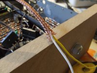
The issue is feeding the 'AC' to a remote rectifer PSU via this lead - all the noise from rectification gets radiated from the wire. Put the rectifiers next to the transformer and feed raw DC if you must. Wire should be a twisted pair - the noise is from 50Hz up so shielding alone may not help at all
If the rectifiers are part of the clock board end so you can't do this easily, try adding small 10nF film or ceramic caps across the AC wire at both ends of the cable - it may be enough to suppress things a bit.
If the rectifiers are part of the clock board end so you can't do this easily, try adding small 10nF film or ceramic caps across the AC wire at both ends of the cable - it may be enough to suppress things a bit.
Last edited:
I've previously been told that the rectifiers must be next to the smoothing cap for best results - so we have a conflict of interests in the layout, right?
I've tried a twisted pair and the effect on the radio is the same. I've now taken the two braided layers off some interconnect wire and am fitting them over the twisted pair. I'm not holding my breath but I want to try it at least.
I wondered about caps and with your suggestion I will certainly try that next.
Thanks,
Simon
No conflict - you need to keep the transformer and the rectifiers and the reservoir caps all close together. Such loops are incredibly noisy.
So to do remote PSUs right, you need to send smoothed DC down the link and have additional local reservoir caps in the load at least. *
If the additional small caps don't work, a bit of brute force should - add a small resistors in each leg of your output from the transformer, 4.7 - 10ohms each if you can stand the resulting voltage drop. It will reduce emissions because it is effectively a low-pass filter with the (remote) reservoir cap.
(* and that's one good reason why, for example, Naim's offboard supplies are all regulated - greatly enhanced noise immunity)
Last edited:
I wondered about resistors but stalled due to lack of knowledge! Thanks again.
Clock psus are a bad idea off-board, I've learnt this before. The others are working just fine. When I was new to modding I did a tx/smoother/5V reg offboard and there was a high-pitched noise on the audio and eventually the clock failed. I'm sure it was because of the offboard PSU.
Clock psus are a bad idea off-board, I've learnt this before. The others are working just fine. When I was new to modding I did a tx/smoother/5V reg offboard and there was a high-pitched noise on the audio and eventually the clock failed. I'm sure it was because of the offboard PSU.
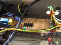
I considered pre-regs off-board but me buddies said no, don't do it! Maybe I should just try it anyway. Most lines have voltage to spare although the 7220, 7310 and D1 output stage supplies all have CLRC filtering now, partly with the aim of dropping volts to reduce player heat - this is a warm machine.
OK, the shielding and 22nF caps at each end have made no difference to killing that radio station but the funny thing is I just tried tuning into other stations and everything worked just fine. It just ruins Rother FM LOL
I've had enough of this now, time to move on.
I've been in the attic looking for my 'scope but sadly I think I've lost it. I was just thinking it's time to learn to drive it. I'd better scour Ebay for an old cheapie.
I've had enough of this now, time to move on.
I've been in the attic looking for my 'scope but sadly I think I've lost it. I was just thinking it's time to learn to drive it. I'd better scour Ebay for an old cheapie.
Last edited:
I also dropped in some transient diodes across live-neutral for spike killing.
edit: been looking on Ebay and there are some 'scopes that may finish cheaply, such as: http://www.ebay.co.uk/itm/Gould-Adv..._Measurement_Equipment_ET&hash=item3cba111811 - but how do I know what to buy??
edit: been looking on Ebay and there are some 'scopes that may finish cheaply, such as: http://www.ebay.co.uk/itm/Gould-Adv..._Measurement_Equipment_ET&hash=item3cba111811 - but how do I know what to buy??
Attachments
Last edited:
off board power
What would happen if you put all the transformer/rectifier/crc/clc offboard and then inductors/ferrit bead/Oscon polymers right at the consumer.
your observations are making me re think what is going on inside my one box layout. I have been thinking I should put metal wall around the signal areas with the transformers on the other side of the wall.
Yeah, I wouldn't worry about that. The dac datasheet allows a bit of leeway on these voltages, so it's obviously not critical. Making it 'quiet' seems far more important IME than hitting an exact DC voltage differential.
Note some Philips players are known for having a -6v supply here!
Note some Philips players are known for having a -6v supply here!
Cool. I've got a 1uF / 0.33R combo between the pins of -15V and -5V now. Just having a little listen and might then do some more work on it but it's such a pain to take the audio board out. This is tacked on the top of the pins.
The sound seems very open this evening, with superb clarity and transient attack on plucked guitar and clean vocals. Those little tweaks obviously didn't hurt things. I know the bass can be deeper on this Diana Krall CD but I'm left wondering if that's a player issue or mains impedance, which I suspect is very high in this house sadly. Cymbals are pleasing at the minute but again I know they could potentially hit harder (more metallic) and with more shimmer and air. I'd better get that cap in and compare....!
The sound seems very open this evening, with superb clarity and transient attack on plucked guitar and clean vocals. Those little tweaks obviously didn't hurt things. I know the bass can be deeper on this Diana Krall CD but I'm left wondering if that's a player issue or mains impedance, which I suspect is very high in this house sadly. Cymbals are pleasing at the minute but again I know they could potentially hit harder (more metallic) and with more shimmer and air. I'd better get that cap in and compare....!
Last edited:
Very definitely.No conflict - you need to keep the transformer and the rectifiers and the reservoir caps all close together. Such loops are incredibly noisy.
So to do remote PSUs right, you need to send smoothed DC down the link and have additional local reservoir caps in the load at least. *
If the additional small caps don't work, a bit of brute force should - add a small resistors in each leg of your output from the transformer, 4.7 - 10ohms each if you can stand the resulting voltage drop. It will reduce emissions because it is effectively a low-pass filter with the (remote) reservoir cap.
Keep all the loop areas as small as possible and particularly for transmitters where large pulsed currents are involved.
- Status
- This old topic is closed. If you want to reopen this topic, contact a moderator using the "Report Post" button.
- Home
- Source & Line
- Digital Source
- Arcam Alpha mods