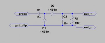
Thanks JedRF sniffer... if you don't have an oscope, but think you have an oscillation problem, you can hook this up to a DC meter for an idea whether there's oscillation present (only with no signal applied to the amp.
Ill build that up and give it a shot !
bob
10n has a 1.6k Xc at 10khz, so if you think the circuit is killing the oscillation when you try to read it, try changing the caps to 2.2n or 3.3n
we used 0.1uf mylars as burn in test loads with a 50khz signal applied. this would insure all of the heat dissipation during burn-in test was generated in the amplifier, not wasted in the load. i'll tell you what, two racks of 20 APT-1 amps each, dissipating a couple hundred watts in each amp, kept the initial functional test tech toasty warm on those cold Cambridge winter mornings...
we used 0.1uf mylars as burn in test loads with a 50khz signal applied. this would insure all of the heat dissipation during burn-in test was generated in the amplifier, not wasted in the load. i'll tell you what, two racks of 20 APT-1 amps each, dissipating a couple hundred watts in each amp, kept the initial functional test tech toasty warm on those cold Cambridge winter mornings...
Last edited:
Now that would be a site !!!!! Jed you have any photos ???10n has a 1.6k Xc at 10khz, so if you think the circuit is killing the oscillation when you try to read it, try changing the caps to 2.2n or 3.3n
we used 0.1uf mylars as burn in test loads with a 50khz signal applied. this would insure all of the heat dissipation during burn-in test was generated in the amplifier, not wasted in the load. i'll tell you what, two racks of 20 APT-1 amps each, dissipating a couple hundred watts in each amp, kept the initial functional test tech toasty warm on those cold Cambridge winter mornings...
bob
sorry, never been much of a camera bug... Tom Holman had a bunch of pictures though that were taken and given to him in a photo album when he went to LucasFilm. one of the pictures that a couple of the techs staged as a joke (we did get a talking to about it by the tech supervisor later) was where we charged up one of the P/S caps, and discharged it with a screwdriver as the picture was taken with surprised looks on our faces.... we must have timed it right as the mini-fireball was visible in the picture... there were quite a few in-house jokes.... one of them was a letter on Sony letterhead instructing US Sony reps to kidnap Tom Holman and Mark Dinsmore (Tom's assistant). there was also the amp test bench "Panic Button" (which actually worked) which was a huge military surplus circuit breaker with a foot long lever on it, and a big red button (labeled "PANIC BUTTON") that would send a 12V trip signal to the circuit breaker. the circuit breaker would kill all the power to the bench. it was put together as a joke but it really worked.... i wish i had pictures of that too....
RF sniffer... if you don't have an oscope, but think you have an oscillation problem, you can hook this up to a DC meter for an idea whether there's oscillation present (only with no signal applied to the amp.
I got hold of an old Navy scope made by Dumont. seems to work fine, just need to find probes, and a crane to lift it.
bob
from what I can find on google 20 mhz....remains to be seen but Ill find out.How fast is it?
I have an old Navy scope too, 100Khz.
bob
they were called "cat's eye" buttons. they originally came from japan, as did the output transistor sockets, but i don't remember the name of the manufacturer (of either). the transistor sockets got discontinued in 1982 or 3. i spent monthe digging in Far-East catalogs looking for something even similar. you would think there would be at least one other manufacturer that made something very much like it, but i never did find a direct replacement. i came up with a workaround which worked pretty well. if you ever see the later model amps, you will see what i mean.
i would think that the cat's eye buttons might still be in production somewhere, since that type of push switch usually requires something like it as an indicator.. what is wrong with the buttons you are replacing?
i would think that the cat's eye buttons might still be in production somewhere, since that type of push switch usually requires something like it as an indicator.. what is wrong with the buttons you are replacing?
they were called "cat's eye" buttons. they originally came from japan, as did the output transistor sockets, but i don't remember the name of the manufacturer (of either). the transistor sockets got discontinued in 1982 or 3. i spent monthe digging in Far-East catalogs looking for something even similar. you would think there would be at least one other manufacturer that made something very much like it, but i never did find a direct replacement. i came up with a workaround which worked pretty well. if you ever see the later model amps, you will see what i mean.
i would think that the cat's eye buttons might still be in production somewhere, since that type of push switch usually requires something like it as an indicator.. what is wrong with the buttons you are replacing?
Thanks, my mute button indicator is a little funny, I have to tap it to get the eye to close.
Nothing I cant live with, but I have never seen buttons/indicators like the APT used.
Made me think why the hell hadn't other manufacturers caught on. Brilliant idea.
Transistor sockets..... yeah I had been looking for the same type sockets, with no luck what so ever. I was very,very carefull when I did the rebuild on my amp, not to damage one.
bob
Push Button Switch Push Button Switch - Shogyo.Com
shogyo makes a rectangular version of the "cat's eye" actuator, they may have been the makert of the round one... i'll keep looking
shogyo makes a rectangular version of the "cat's eye" actuator, they may have been the makert of the round one... i'll keep looking
Hi Jed, I am trying to contact you to find out about my APT-1. Any hope on it?
I have 4 of them, all recently serviced (by myself)
Anything I can assist with ?
Tripped over this thread
I actually have one of those, mine has a different face plate, a rack mount style. The terminal strips are there as described. However, I believe if memory serves, mine has only standard RCA inputs.
I have at least two more standard amps as well. Loved them. Could not bare to sell, so held on. Good to know there is solid advice out there for rejuvenation if needed!
Somehow migrated to Brystons, these lie dormant for now.....strangely all 3 face plates have aged very differently in color...but I got them all used in the Chicago market. Suspect very strongly Simon's Audio Consultants brought them here.
i remember also a pro-audio variant that was made. the protection/ input board was modified (actually a completely different board was produced) with cannon plugs and a terminal strip for balanced inputs, and holes cut in the rear panel of the belly pan for the cannon plugs. i only saw a handful of them go through the assembly line. they were available by special order only.
I actually have one of those, mine has a different face plate, a rack mount style. The terminal strips are there as described. However, I believe if memory serves, mine has only standard RCA inputs.
I have at least two more standard amps as well. Loved them. Could not bare to sell, so held on. Good to know there is solid advice out there for rejuvenation if needed!
Somehow migrated to Brystons, these lie dormant for now.....strangely all 3 face plates have aged very differently in color...but I got them all used in the Chicago market. Suspect very strongly Simon's Audio Consultants brought them here.
Additional trivia
That professional version is serial #H01005, signed off and tested by "KS"
The front says "Professional Amplifier 1". It also has a knob on the back to fine tune another setting...if I recall, it seemed to be a sensitivity of some kind...one of the settings did allow it to perfectly match the regular version.
I have a strange feeling I may have had the techs at A.C. convert the plugs for me to avoid expensive cables that would not have matched anything else I had....
Could post pics if any one wants...
- Home
- Amplifiers
- Solid State
- APT 1 power amp – undeservedly forgotten