the 10W figure comes from the data sheet, with the 1W listed also. i'm guessing the 1W figure is free air, and the 10W is heat sinked and the collector tab maintained at 25C. the 1W figure is sufficient, as the devices are run at something like 20mA or less.
I take it those were the predrivers, were they mounted to the heat sink? Probably not.
MPSA92/42 are probably the same die, just in a different package - could use a slip on tab heat sink. ft=50M, Ccb=3pF:
www.fairchildsemi.com/ds/MP/MPSA42.pdf
Guys
Reading these posts I cant help but think how cool it would be to create a 2011 version of the APT AMP, maybe another APT preamp too.
Id visualize being true to the original. More a reissue. I guess thats what im doing with my APT 1.
A complete and very carefull rebuild. Id love to start with brand new circuit boards. Real nice 2 oz fiberglass....
sounds like the cap in the servo (C16) has dried out. i think that amp is a rev2, so it should match the schematic. also replace C1, C26, C27 since those are in the input stage C1 is the input coupling cap, C26 is the filter for the current source supply, and C27 is the bypass for the input buffer emitter loads.
Well, you must have mystical powers! I did replace C16 with a new one and now the amps works! Listened to music last nite! Now I need to replace the caps on the other channel and I should be finished! I also put a Nichicon ES bipolar in place of the regular electrolitic C1. Do you think it is a good idea? That seems to be the only cap on the signal path.
After this accomplishment, I went back to the preamp. No signal goes through it and the power led does not turn on. But moving the balance or tone knobs produces click on the output. Any suggestions? I am planning to replace all small caps and substitute all 10 ICs with TLE 2072 as suggested previously. Should I use the bipolar Nichicon muse on the signal path? ( 3or 4 10uF 35V caps). I am also planning to substitute all power supply diodes with Fairchild FFP08S60STU (lower switching noise). Are these potential improvement worthwhile in your opinion? Any further suggestion?
Thanks!
Antonio
Well
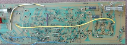
Guys finally got 1 amp board cleaned. Im going to start the build soon, I have to get my parts order all finished.
Im going to build one board at a time using the other as a reference.
Im thinking also relocate the jumper wires to the foil side of the boards, makes fo less clutter.
bob
Guys finally got 1 amp board cleaned. Im going to start the build soon, I have to get my parts order all finished.
Im going to build one board at a time using the other as a reference.
Im thinking also relocate the jumper wires to the foil side of the boards, makes fo less clutter.
bob
Attachments
Last edited:
Well, you must have mystical powers! I did replace C16 with a new one and now the amps works!
most logical choice.... no "Magnificent Karnak" powers required....

Listened to music last nite! Now I need to replace the caps on the other channel and I should be finished! I also put a Nichicon ES bipolar in place of the regular electrolitic C1. Do you think it is a good idea? That seems to be the only cap on the signal path.
if you ever have negative dc offset on a preamp output, it won't show up at the amp input with a bipolar, but it might with a polarized lytic.
After this accomplishment, I went back to the preamp. No signal goes through it and the power led does not turn on. But moving the balance or tone knobs produces click on the output. Any suggestions? I am planning to replace all small caps and substitute all 10 ICs with TLE 2072 as suggested previously.
check the +/-18V rails. you may have one or both regulators toasted. replace all the lytics in the power supply as well. there's also a +/-12V set of rails for the phono preamp IIRC. in the schematic there are also a couple of transistors in the rails for the phono preamp that at first glance look like regulators. they're actually capacitance multipliers. the capacitors on the bases are multiplied by the beta of the transistor. replace those caps too.
Should I use the bipolar Nichicon muse on the signal path? ( 3or 4 10uF 35V caps). I am also planning to substitute all power supply diodes with Fairchild FFP08S60STU (lower switching noise). Are these potential improvement worthwhile in your opinion? Any further suggestion?
Thanks!
Antonio
the bipolars are ok. as i said earlier, dc offset of the wrong polarity will leak through polarized lytics (lytic caps are "descended" from "electrolytic rectifiers" used in battery chargers back in the early 20th century, and act somewhat like a forward biased diode when the polarity is reversed... often with the side effect of them popping....)
Well
Guys finally got 1 amp board cleaned. Im going to start the build soon, I have to get my parts order all finished.
Im going to build one board at a time using the other as a reference.
Im thinking also relocate the jumper wires to the foil side of the boards, makes fo less clutter.
bob
i'd keep the wires on top of the board. it reduces clutter on the solder side, and the top side is already "cluttered" so a couple of jumpers don't matter much. besides one of those jumpers is the feedback to the inverting input of the diff amp. better to keep it as far away as possible from the power supply rail wires, to keep magnetically induced distortion down. you really don't want PVC insulated wire jumpers on the solder side. if you ever have to desolder anything along their paths, they'll get in the way, and are prone to getting the insulation melted off if you slip with the soldering iron.
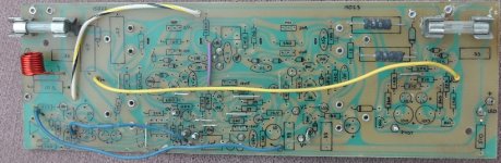
More APT photos. biguns!
Guys
I want to share some of the info I have found on the APT amp.
here is a rev 4 amp board layout and a protect board layout.
Too big to upload to the forum so I have the pics here.
Ill keep adding photos as work progresses.
Apt 1 amplifier project Photo Gallery by bob at pbase.com
bob
Guys
I want to share some of the info I have found on the APT amp.
here is a rev 4 amp board layout and a protect board layout.
Too big to upload to the forum so I have the pics here.
Ill keep adding photos as work progresses.
Apt 1 amplifier project Photo Gallery by bob at pbase.com
bob
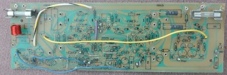
Guys.
If your interested, I have a few more photos up of my APT rebuild.
My photo site is here
Apt 1 amplifier project Photo Gallery by bob at pbase.com
bob
If your interested, I have a few more photos up of my APT rebuild.
My photo site is here
Apt 1 amplifier project Photo Gallery by bob at pbase.com
bob
Guys
This is prolly a question for Uncle Jed but im going to throw it out there.
My amp boards are revision 3. amp serial 1900
Looking at the schematic R6 going from emitter of Q1 to base of Q2 & R13 going from base of Q3 to emitter of Q4 both showing as 360 ohm resistors, also that value is printed on the board. What I'm seeing on the board are 39 ohm resistors. maybe this was a change or possibly a mistake made at the factory.
Also, the zeners Im seeing on the boards 1N5231B all 5.1 volt.
one more thing, C1 the input cap on the board printing shows 1uf, schematic shows 10 uf. my thoughts are 10 is more like it.
Any ideas out there ????
Looking at a board layout for revision 4, these values were changed, all to 39 ohm. Im thinking my boards are more like a revision 3.5
bob
Last edited:
the emitter resistors in the diff amp were changed to 39 ohms. a later rev actually put a 100 ohm pot there (and did away with the one in the servo). go with 10uf for C1 for now. yes the zeners were changed to 5.1 volts, which have a lower tempco than the 4.7 volt zeners and are only a difference of 0.4V the basic operation of the amp remains about the same. the silk screen values often lagged behind the value changes or were incorrect. they tightened up the silkscreen changes in later revs
Preamp progress (or regress..)
Well, as planned, i did work on the preamp.... replaced all electrolytics with high grade Nichicons and all the ICs (except the 3 in the buffer stage... not planning to listen to tapes anymore...) with TLE2072 (expensive! they cost about 3.50 each and one needs 11 of them...) as suggested. Went to test the preamp with the recently fixed APT-1. Very silent, and it rocks with music! But only with the tones in defeat! If I insert the tones, volume drops considerably on both channels! Tone knobs seem to work as they should, but the volume is low, even with volume knob at max. Checked that all caps and ICs are correctly mounted, not seen anything obviously wrong, moved the trim pots... Any suggestion?
Also, I noticed that there is a button rectifier next to the transformer. Looks weak.. any suggestion to replace it with something better? Space is limited!
Thanks for any advice!
check the +/-18V rails. you may have one or both regulators toasted. replace all the lytics in the power supply as well. there's also a +/-12V set of rails for the phono preamp IIRC. in the schematic there are also a couple of transistors in the rails for the phono preamp that at first glance look like regulators. they're actually capacitance multipliers. the capacitors on the bases are multiplied by the beta of the transistor. replace those caps too.
the bipolars are ok. as i said earlier, dc offset of the wrong polarity will leak through polarized lytics (lytic caps are "descended" from "electrolytic rectifiers" used in battery chargers back in the early 20th century, and act somewhat like a forward biased diode when the polarity is reversed... often with the side effect of them popping....)
Uncle Jed
I have a question for you, the 2SC1345's used for Q1, Q10(bias)Q4 are these hfe sensitive especially the bias transistor.
Should Q2 & Q3 and Q2 & Q4 be matched ?
I have a source for replacement 1345's but the leads are reversed and in a to92 package from bdent.
I have 10 original 1345's exactly like in the amplifier the hfe ranges 450-600
Also is it ok to use the later drivers Q15 = 2SC2344 Q16 = 2SA1011 to replace the earlier types?
bob
Last edited:
no not really. the 1345's at the input are unity gain buffers. the bias transistor circuit isn't fussy about beta either (at least within the normal beta range of 1345's). it's best to use the flat 1345's for bias transistors, and use the TO-92 ones for the input stage buffers. it's kind of difficult to get the round side of the case to make good thermal contact with the heat sink.
with the later drivers, it should work. i'm trying to remember if the value of the miller caps (C4, C9) changed with the change in drivers. if you have access to an amp with later drivers, check the miller caps to see if they're 33pf instead of the original 25pf. other than that there wouldn't be much that would change since everything else in the circuit is pretty much not dependent on device characteristics. .
with the later drivers, it should work. i'm trying to remember if the value of the miller caps (C4, C9) changed with the change in drivers. if you have access to an amp with later drivers, check the miller caps to see if they're 33pf instead of the original 25pf. other than that there wouldn't be much that would change since everything else in the circuit is pretty much not dependent on device characteristics. .
my first question is where the Mode control and the L-R switch are set?
maybe bad trim pots?, i'd go through the tone circuit one step at a time and see where the signal disappears. a little "sniffer amplifier" like what Radio Shack used to sell is good for this, or build one with an LM386, 9V battery and a speaker. an oscope might also be helpful here too. one possibility is that with the increased bandwidth of the TLE2072, the high freq shelving filter might actually be causing this stage to oscillate ultrasonically. if so this (IC10) might be the exception where the op amp should be a TL072 instead. the other possibility here is that something is wrong with the buffer Q14, Q15. this is an interesting circuit Q14 is a unity gain buffer, and Q15 is a current source load for Q14.
it could also be a dirty tone defeat switch.
Well, as planned, i did work on the preamp.... replaced all electrolytics with high grade Nichicons and all the ICs (except the 3 in the buffer stage... not planning to listen to tapes anymore...) with TLE2072 (expensive! they cost about 3.50 each and one needs 11 of them...) as suggested. Went to test the preamp with the recently fixed APT-1. Very silent, and it rocks with music! But only with the tones in defeat! If I insert the tones, volume drops considerably on both channels! Tone knobs seem to work as they should, but the volume is low, even with volume knob at max. Checked that all caps and ICs are correctly mounted, not seen anything obviously wrong, moved the trim pots... Any suggestion?
Also, I noticed that there is a button rectifier next to the transformer. Looks weak.. any suggestion to replace it with something better? Space is limited!
Thanks for any advice!
Last edited:
Mode in the middle, L-R switches in the down position.my first question is where the Mode control and the L-R switch are set?
maybe bad trim pots?, i'd go through the tone circuit one step at a time and see where the signal disappears. a little "sniffer amplifier" like what Radio Shack used to sell is good for this, or build one with an LM386, 9V battery and a speaker. an oscope might also be helpful here too.
Will try with a scope...
one possibility is that with the increased bandwidth of the TLE2072, the high freq shelving filter might actually be causing this stage to oscillate ultrasonically. if so this (IC10) might be the exception where the op amp should be a TL072 instead.
Will a tantalum cap across the power supply terminals help?
the other possibility here is that something is wrong with the buffer Q14, Q15. this is an interesting circuit Q14 is a unity gain buffer, and Q15 is a current source load for Q14.
it could also be a dirty tone defeat switch.
Will check these too...
tantalum? no, definitely no....... tantalums are an accident waiting to happen, they seem to have one failure mode, and that's a dead short. they were excluded from all of APT equipment designs just for that reason. it's better to put 0.1uf ceramic or mylar bypasses right at the power pins of the ic directly to the nearest ground plane. whichever will fit NEATLY under the board.
of course the military uses tantalums in their stuff, but their solution to the reliability problems is this: use capacitors rated at twice (or more) the operating voltage. this is usually a quite expensive way of doing it, but it seems to solve most of the problems with "tantalum sudden death syndrome" (but also at the cost of a higher ESR in the caps)
of course the military uses tantalums in their stuff, but their solution to the reliability problems is this: use capacitors rated at twice (or more) the operating voltage. this is usually a quite expensive way of doing it, but it seems to solve most of the problems with "tantalum sudden death syndrome" (but also at the cost of a higher ESR in the caps)
it could also be a dirty tone defeat switch.
Well indeed after lots of tracing it seems that the switch is defective! The signal gets to either side posts (4 and 6 on the schematics) but never gets out on center 5 ! Interestingly, it is never on both side posts, one or the other... bridging either couple of posts brings back the volume with tones on or slightly reduces it on defeat.
Now, how to clean it without breaking it? Will a replacement be available? Maybe I need to replace all of them?
From the little I listened, the rebuilt and improved pre+ power amps sound great, very silent and punchy... Can't wait to connect it to a good couple of speakers and crank it up!
repairing these switches is a risky business. i suppose you could bleed some deoxit down into the switch through the ball and socket, (or soak them overnight in a solution of 20% deoxit and 80% alcohol (isopropyl in 99% strength, not the 70% strength available as rubbing alcohol). the only other way is to disassemble them, but they're easily damaged, or the small parts are easily lost, or worse, easily misaligned upon reassembly. they were originally filled with a grease compound, which has probably dried out and hardened. the overnight soak is probably the best way. you will have to operate the switch while immersed to work the solution into the switch enclosure.
i have rebuilt these switches before, but reassembly is not easy. it's possible the original grease blob in the switch was somewhat of an assembly aid to keep the parts aligned and in place while the switch was being assembled.
i have rebuilt these switches before, but reassembly is not easy. it's possible the original grease blob in the switch was somewhat of an assembly aid to keep the parts aligned and in place while the switch was being assembled.
Last edited:
i have rebuilt these switches before, but reassembly is not easy. it's possible the original grease blob in the switch was somewhat of an assembly aid to keep the parts aligned and in place while the switch was being assembled.
I think that the grease is an important part of the switch. However, I found lots of switches in the Mouser catalog. Any idea of which one I should get to replace all of them? Something like DPDT on-on? (double pulse double trow)? Interestingly, there is no resistance measured with an ohm meter across the poles of the switch but the pre still does not work; but it works if the switch pins are bridged! I tried also a switch from another position and got the same result!
Left channel is very distorted with strong bass. Maybe the trimmer is bad? The other channel works great, no noise, great dynamic and a sparkling sound!
- Home
- Amplifiers
- Solid State
- APT 1 power amp – undeservedly forgotten