If your still interested in doing a "traditional" OPT with the DC current running through the primary...
Here are some starting points....
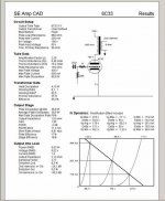
Figure running the 600 ohm plate load....
Idle at 180V @ -60V BIAS @ 250mA DC current....
This is about 13.5 Watts output..... Which is roughly 88V RMS with 150mA AC across the primary winding at full power output....
Here are target numbers for good bandwidth..according to a plate load of 600 ohms and an "AVERAGE" plate resistance of 150 ohms...averaged over one cycle at full power output....
5.7H Inductance will get your -3dB down to roughly 6Hz....
2mH leakage will get your -3dB up to about 60kHz......
For wire gauge I would use #27 on the primary....
Keep in mind to keep the combined , summed AC flux density + DC flux density excursion to a 13.5 kG limit.... normally I limit this to 12kG in PP design...but in SE design the gap allows a bit more usuable flux swing from axis tilit...
I choose a core size of EI-150 laminations of M6....using a 2" stack..this would be roughly a 2.8" AREA when butting the E and I lams to make the gap....
Setting the AC flux density to 6.7 kG at lowest frequency for 30 Hz...Usually I use 20 Hz but need to compromise for this design at the moment...This relates to % core distortion at full ratted power output at 30 Hz...
I wind up with roughly 3500 turns for the primary...now this allows roughly 6.7kG left over headroom for the DC flux density...
Apply the DC flux density equation to set it for 6.7kG...leaving the GAP as the unknown... this will figure the GAP.....
Then plug the GAP into the inductance equation to see if you hit the minimum target of 5.7H ....depending on how close this is...you may need to make changes and re-iterate some of the process to tighten up the design....
Chris
Here are some starting points....
Figure running the 600 ohm plate load....
Idle at 180V @ -60V BIAS @ 250mA DC current....
This is about 13.5 Watts output..... Which is roughly 88V RMS with 150mA AC across the primary winding at full power output....
Here are target numbers for good bandwidth..according to a plate load of 600 ohms and an "AVERAGE" plate resistance of 150 ohms...averaged over one cycle at full power output....
5.7H Inductance will get your -3dB down to roughly 6Hz....
2mH leakage will get your -3dB up to about 60kHz......
For wire gauge I would use #27 on the primary....
Keep in mind to keep the combined , summed AC flux density + DC flux density excursion to a 13.5 kG limit.... normally I limit this to 12kG in PP design...but in SE design the gap allows a bit more usuable flux swing from axis tilit...
I choose a core size of EI-150 laminations of M6....using a 2" stack..this would be roughly a 2.8" AREA when butting the E and I lams to make the gap....
Setting the AC flux density to 6.7 kG at lowest frequency for 30 Hz...Usually I use 20 Hz but need to compromise for this design at the moment...This relates to % core distortion at full ratted power output at 30 Hz...
I wind up with roughly 3500 turns for the primary...now this allows roughly 6.7kG left over headroom for the DC flux density...
Apply the DC flux density equation to set it for 6.7kG...leaving the GAP as the unknown... this will figure the GAP.....
Then plug the GAP into the inductance equation to see if you hit the minimum target of 5.7H ....depending on how close this is...you may need to make changes and re-iterate some of the process to tighten up the design....
Chris
My secad software never seems to give an rp value for the 6c33 less than 250 ohms which results in otps primary impedance values around 800-1000ohms to maximize distortion/power trade off.
Also the 2nd harmonic distortion figures are quite high and never really much below 10% at full ouput unlike eg 300b which are consistently around 5%.
However the rp inconsistency vs usual practice of using the 6c33 with 600ohm otp is surprising .
Best results are around 270v on the plate and 150ma.
Protos....
You would need to see the model in the software...to see how they are getting the rp.....
Based on the curve sheets...I get roughly 150 to 160 ohms AVERERAGE over one complete cycyle...
I think I know what is happening....
The plate resistance is not a "fixed" number with a tube....
It varies.... It is only fixxed at IDLE....and that is what I believe your software is using... at 270 at the plate...the rp is indeed closer to 250 ohms.... But if you look at where I choose my idle point...it is much lower...
WHen you figure for rp ...you need to take the AVERAGE rp over one sine-wave cycle....I typically use the full AC swing you would get at full power output....
I was able to finish a OPT design for this tube.... The core would be a EI-125 with 1.25"stack .... I achieved -3db points at 7 Hz and at 57kHz.... If anyone is interested let me know..
Chris
Drat !
This posting files is so complicated here.
Moderator: When I try to reply with a written reply plus an attachment that is incompatible with the website first of all the whole reply is completely erased and then I have no way to get back to the last webpage with the back button.I have to start all over again.
very frustrating!!
I got some bitmap curves that I had to tansform to jpeg but they were too large.
Hi
Finished my amp a few month ago, with home made transformers. It was an experiment, combining two SE triodes to a transformer with to primary´s. Had to compromise a little because of lack of pace in the core´s.
2 * 1380windings as primarys
4 * 144windings as secundary (4ohm) + 2 * 72windings (8ohm)
36watt <3.5%THD, 30watt <3%THD.
TDH at 1Watt = <0.05%
25hz-18Khz -1dB. 12Hz-31Khz -3dB (1Watt output) nofeedback
25hz-15Khz -1dB. 12hz-27Khz -3dB (30Watt output) nofeedback
Best regards
Kim Olesen, www.micro-io.dk
Positive grid bias
Hi,
This is a bit different to the current thread so we can move over to a fresh one if you'll like but as you seem to be very 6C33C savvy here I thought I'd fire some questions at you all.
I'm working on a 4 * 6C33C-B class A push-pull amp design. In order not to cook the tubes too fast I'm looking at 150V HT and a quiescent current through each valve of about 330mA. The grid would be at about -32 Volts using cathode bias.
I've not done too many sums as yet but its clear that when the Vgc is at 0V the anode will still be at about 40V and the current in each valve will only be about 550mA.
BTW there is another data sheet of sorts at
http://www.mclink.it/com/audiomatica/tubes/6c33c.htm
Anyhow, question 1: its quite common to be able to drive power valve grids positive; Class A2. Does anybody have information on if you can do this with a 6C33C-B?
Question 2 (to Alastair E) - where did you get the bits to wind your transformers from")
cheers
Stephen
Hi,
This is a bit different to the current thread so we can move over to a fresh one if you'll like but as you seem to be very 6C33C savvy here I thought I'd fire some questions at you all.
I'm working on a 4 * 6C33C-B class A push-pull amp design. In order not to cook the tubes too fast I'm looking at 150V HT and a quiescent current through each valve of about 330mA. The grid would be at about -32 Volts using cathode bias.
I've not done too many sums as yet but its clear that when the Vgc is at 0V the anode will still be at about 40V and the current in each valve will only be about 550mA.
BTW there is another data sheet of sorts at
http://www.mclink.it/com/audiomatica/tubes/6c33c.htm
Anyhow, question 1: its quite common to be able to drive power valve grids positive; Class A2. Does anybody have information on if you can do this with a 6C33C-B?
Question 2 (to Alastair E) - where did you get the bits to wind your transformers from
cheers
Stephen
Re: Positive grid bias
Just looking at your dissipation in each valve, You say, 150V @ 330mA?
This equates to 49.5 watts dissipation............
This amp is going to be HOT!
The problem with the 6C33, is the heat generated causes problems with the socket connections after a while--Its generally thought to keep dissipation under 40 W plate for reliability, Less is better if you can cope with class AB near full O/P!
Youll need to allow at least three inches between each valve to allow sufficient cooling too, Use thick wire to connect the socket lugs up with and wrap around the lugs to act as heat-sink for them....
Use something beefy like a 5687/7044 to drive the grids +ve, these beasts can sink some current!
Currently Im using a 7044 to drive 6c33 in a circlotron Ive bread-boarded--They work quite well for the job.......
The parts for the O/P Tx I got from a local transformer maker, He had everything needed including the wire and formers..... If I recall correctly the 'kit of parts cost only around 20 pounds for everything to do three Tx
S Goodwin said:Hi,
This is a bit different to the current thread so we can move over to a fresh one if you'll like but as you seem to be very 6C33C savvy here I thought I'd fire some questions at you all.
I'm working on a 4 * 6C33C-B class A push-pull amp design. In order not to cook the tubes too fast I'm looking at 150V HT and a quiescent current through each valve of about 330mA. The grid would be at about -32 Volts using cathode bias.
I've not done too many sums as yet but its clear that when the Vgc is at 0V the anode will still be at about 40V and the current in each valve will only be about 550mA.
BTW there is another data sheet of sorts at
http://www.mclink.it/com/audiomatica/tubes/6c33c.htm
Anyhow, question 1: its quite common to be able to drive power valve grids positive; Class A2. Does anybody have information on if you can do this with a 6C33C-B?
Question 2 (to Alastair E) - where did you get the bits to wind your transformers from
cheers
Stephen
Just looking at your dissipation in each valve, You say, 150V @ 330mA?
This equates to 49.5 watts dissipation............
This amp is going to be HOT!
The problem with the 6C33, is the heat generated causes problems with the socket connections after a while--Its generally thought to keep dissipation under 40 W plate for reliability, Less is better if you can cope with class AB near full O/P!
Youll need to allow at least three inches between each valve to allow sufficient cooling too, Use thick wire to connect the socket lugs up with and wrap around the lugs to act as heat-sink for them....
Use something beefy like a 5687/7044 to drive the grids +ve, these beasts can sink some current!
Currently Im using a 7044 to drive 6c33 in a circlotron Ive bread-boarded--They work quite well for the job.......
The parts for the O/P Tx I got from a local transformer maker, He had everything needed including the wire and formers..... If I recall correctly the 'kit of parts cost only around 20 pounds for everything to do three Tx
Re: 6c33c-b parafeed SET
Jaime,
Did you ever built the parafeed 6c33c-b?
Thanks.
Jaime said:Yvesm and Alastair E
I would like to wind the indutance and the OP tranfo for a 6c33c-b parafeed SE.
It is possible with the program?
Which it forms I do it?
best regards Jaime
Jaime,
Did you ever built the parafeed 6c33c-b?
Thanks.
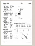
Since this thread picked up again I am attaching a screen shot of the results discussed previously.Mainly that with secad software at least it seems impossible to achieve 15w single ended outputs with 600 ohm otp and low B+/ high current.I am using around 260V on the tube and 160 ma w 1000 ohm otp which gives around 13-14W.
A trick that has worked for me with single-ended 6c33c's is to drive it with an asymmetric signal. Proper integration of waveform symmetry between driver tube and the 6c33c can result in higher RMS power with lower THD on the output. Of course simulating this would be beyond SE Amp CAD's capability. But SE Amp cad is still a vert usefull tool.
6c33c's would also probably be good for class A push pull.
6c33c's would also probably be good for class A push pull.
- Status
- This old topic is closed. If you want to reopen this topic, contact a moderator using the "Report Post" button.
- Home
- Amplifiers
- Tubes / Valves
- Anyone wound SE transformer for 6c33c-b?