theChris said:what is the complete schematic fort he P/S. and why 4ohm speakers? IIRC most of the 47xx line doesn't appreciate 4ohm loads as much as the 38xx line. and it also makes a BTL subamp just that much harder.
ummm.. I thought the LM4780 was basically 2 LM3886's in the one package.... 4 ohms, because thats what the speakers are..
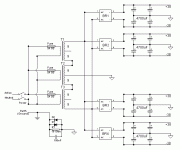
not sure if theres anything wrong with that schematic.. proabably.. but its how the transformers, bridges, and caps will probably be connected..
Attachments
some of the 47xx lines will put out less power into 4ohms @ 10% distortion.
not a big fan of the circuit due to the 4 full wave bridges and the problems with grounding. basically if one chip pulls signifigant power from a rail, it's ground would be different then the other 4. if they are all connected, then why 4 full wave bridges? a single full wave bridge is all that's needed. possibly 2.
not a big fan of the circuit due to the 4 full wave bridges and the problems with grounding. basically if one chip pulls signifigant power from a rail, it's ground would be different then the other 4. if they are all connected, then why 4 full wave bridges? a single full wave bridge is all that's needed. possibly 2.
theChris said:some of the 47xx lines will put out less power into 4ohms @ 10% distortion.
not a big fan of the circuit due to the 4 full wave bridges and the problems with grounding. basically if one chip pulls signifigant power from a rail, it's ground would be different then the other 4. if they are all connected, then why 4 full wave bridges? a single full wave bridge is all that's needed. possibly 2.
yeah whatever... I'm too depressed to think...
li_gangyi said:it's true...but you would have to use the centre-tap..which some trafos dun have...so if it doesn't have a CT..the only way would be to get 2 bridges...or connect 2 primaries together..though some people prefer to have 2 bridges...dunno why???
I'm not sure if that even makes sense...
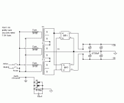
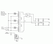
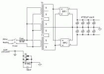
pics are fun. you can also use only 1 full wave bridge if you want. using 2 will give more losses (which is something you wanted as it lowers the supply voltage), but also increases frequency. so a capacitor can be smaller. if not the voltage rails will be higher. this setup may be ideal for a subwoofer amp where IMO the extra caps would allow for more depth.
BTW, you can change capacitance as needed.
(edit - changed attachment to correct connections)
BTW, you can change capacitance as needed.
(edit - changed attachment to correct connections)
Attachments
theChris said:pics are fun. you can also use only 1 full wave bridge if you want. using 2 will give more losses (which is something you wanted as it lowers the supply voltage), but also increases frequency. so a capacitor can be smaller. if not the voltage rails will be higher. this setup may be ideal for a subwoofer amp where IMO the extra caps would allow for more depth.
BTW, you can change capacitance as needed.
(edit - changed attachment to correct connections)
I dunno what the diodes do.... I chose 4 bridges because it makes it easier... 9400uF per rail for the whole amp won't be enough... but if I'm only running 2 channels, then there would be some huge bank of capacitors on each rail, which would be totally unneeded... I need this amp to be versitile.. so I can run anything from it... (within reason) the capacitors are no problem.... I "have" them...
theChris said:also, i don't think D1 or D2 are needed. what do they do?
this is the 1 BR pic.
I dunno what they do... I stole the circuit from Rod Elliots site and changed it.... as for the fuses... I proabably should use a single 10amp fuse for all the transformers.. cos as it is, if one fuse blows... I'll probably get huge ofset on the output...
"I dunno what they do... I stole the circuit from Rod Elliots site and changed it.... as for the fuses... I proabably should use a single 10amp fuse for all the transformers.. cos as it is, if one fuse blows... I'll probably get huge ofset on the output... you need a fuse rated higher than the output so ya don't blow it when ya switch it on or under heavy loads... maybe 8amp slow blow..."
-that's still a lot of amperage. this amp isn't a 600 watt amp is it?
like i said, the PCB is suipposed to be milled very soon. it likely will be milled tomorrow as i have a class with a teacher who does the isolation part. i'd do that myself, but it's like $2k for the software!
i will keep everyone informed on the miniPCBs. i'll try to make some for the other 27pin chips as well. possibly even some of the 15pin chips.
theChris said:"I dunno what they do... I stole the circuit from Rod Elliots site and changed it.... as for the fuses... I proabably should use a single 10amp fuse for all the transformers.. cos as it is, if one fuse blows... I'll probably get huge ofset on the output... you need a fuse rated higher than the output so ya don't blow it when ya switch it on or under heavy loads... maybe 8amp slow blow..."
-that's still a lot of amperage. this amp isn't a 600 watt amp is it?
like i said, the PCB is suipposed to be milled very soon. it likely will be milled tomorrow as i have a class with a teacher who does the isolation part. i'd do that myself, but it's like $2k for the software!
i will keep everyone informed on the miniPCBs. i'll try to make some for the other 27pin chips as well. possibly even some of the 15pin chips.
its 750VA of transformers... 8 channels... and I should be able to get 75-120watts per channel of music power....
so, yeah.. it is a 600watt amp... lol
Re: Using a LM4765
Hi Deandob. Can you send your LM4765 schematic to me?
ecstabil@sunpoint.net
deandob said:I'm using a LM4765 - sister chip to the LM4780 with 30Wpc for a whole home audio system where I use these as local amps for each room controlled by a touchscreen. When I prototyped these up last year using 1000uF power supply caps I was very pleased with the sound quality, it was able to reproduce dynamics better than my much more expensive DIY discrete MOSFET amp. The design uses the non inverting mode, when I tried inverting I could not stabilise the amp although I suspect trying this on breadboard was not optimal.
Dean
Hi Deandob. Can you send your LM4765 schematic to me?
ecstabil@sunpoint.net
Well seems my post got edited - unsafe practices??
NEway you can also wind some more turns on the primary. This can be done without opening up the transformer, just use some hook-up wire which can carry the rated cuurent, and wind about 10 turns around the whole transformer from one of the primary terminals. Keep checking the voltages every 10 turns, until you have about 22 volt on the secondary. I use it all the time to pull down voltages and it seems to work quite well.
NEway you can also wind some more turns on the primary. This can be done without opening up the transformer, just use some hook-up wire which can carry the rated cuurent, and wind about 10 turns around the whole transformer from one of the primary terminals. Keep checking the voltages every 10 turns, until you have about 22 volt on the secondary. I use it all the time to pull down voltages and it seems to work quite well.
SkinnyBoy said:I got my capacitors for my amp.... sixteen 4700uF 100volt chasis mount... thats 36,700uF per rail...yes, no?? lol...
hmm..
No.
It's 37,600uf per rail.
- Status
- This old topic is closed. If you want to reopen this topic, contact a moderator using the "Report Post" button.
- Home
- Amplifiers
- Chip Amps
- anybody tried a LM4780?


