Re: Question
you need to conect them all...
king30 said:The 4870 chip has 5 V-, and 5 V+ pins. Do they all need to be connected or can I choose just one of each to connect the ps to...Thanks Lee
you need to conect them all...
I completed my LM4780 amp yesterday. I used one chip for both channels. The schematic was the NI version on the data sheets. Initial listening impressions are very positive. I will need to spend more time with it to compare with the LM3875, but I believe the sound is definitely on par.
Building was pretty straightforward took about 2 hours total. Amp was built p2p. The chip has 5 v- and 5 v+ pins. The v- I bent downward and soldered a wire across all of them. The next level up were the two mute pins. I took one end of a 10k resistor and soldered across both and the other end connected to the v- row below.
The next level of pins (these I didn't move from their original positions) were the v+. Again I soldered a wire across all five. I used 2200uf caps, which were connected to the v- and v+ wires. Next level were the 2 +in and 2 gnd pins. The +in pins had a 1k resistor soldered to them which were connected to the rca's. I'll get back to the grounds in a second.
The last row (bent all the way back to the chip) were the out and -in pins . For each side these had the feedback resistor soldered to them and the gain resistor. The two gain resistors were connected together along with the gnd pins from the previous row. I used this grounding point for all the rca's, speakers, caps and ps. Don't know if its text book, but I'm getting zero hum.
The biggest up sides to this chip are:
1. Two channels one chip.
2. Single -v +v connections and one pair of caps
3. Simple Grounding. Can't possibly mess up.
4. Offset. Stable at below 30mv for both channels
5. Noise. There was no background noise or hum. Where with the same ps I had a little hum with the LM3875
6. My wiring usually looks like a rats nest, but with this chip it was much easier to get a clean layout.
I will post some pictures tonight when I get home...Lee
king30 said:I will need to spend more time with it to compare with the LM3875, but I believe the sound is definitely on par.
Me too.

I guess you where using the inverted schematic then...actually what are the 5V for?? can you post a few pics??
I was comparing the NI lm4780 against a NI LM3875. For the 5 v I was not referring to 5 volts but to 5 separate pins. I will post pic's later this evening...Lee
ok...you were referring to 5 positive rails on the chip...haha...what a mix up...will be waiting for the pics...I got the chips on hand already but dunno how to start...as in wiring looks complicated...it took me about 15 mins to get a LM3875TF up and running on my bench...with a small heatsink for testing purposes...hehe
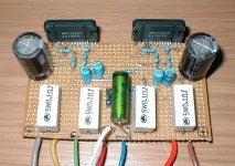
Here are some pictures of my LM4780
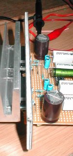
The first picture is the amp sitting on top of the power supply. The heatsink is 6"x6". Ton's of free space inside.
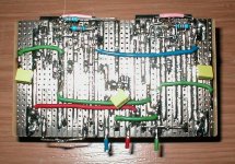
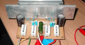
The second picture shows the inside and the third some chip detail. As mentioned before the negative rails are on the bottom. The 10k resistor in the middle is connected to the two mute pins and the neg. rail. Above that you have the positive rail. The two blue resistors are feedback and you can see the gain resistors connected to a central ground point which acts as the star ground for everything in the chasis.
Still doing some listening test, but it is excellent so far...Lee
The first picture is the amp sitting on top of the power supply. The heatsink is 6"x6". Ton's of free space inside.
The second picture shows the inside and the third some chip detail. As mentioned before the negative rails are on the bottom. The 10k resistor in the middle is connected to the two mute pins and the neg. rail. Above that you have the positive rail. The two blue resistors are feedback and you can see the gain resistors connected to a central ground point which acts as the star ground for everything in the chasis.
Still doing some listening test, but it is excellent so far...Lee
An externally hosted image should be here but it was not working when we last tested it.
An externally hosted image should be here but it was not working when we last tested it.
An externally hosted image should be here but it was not working when we last tested it.
SkinnyBoy said:it looks ummm... hmm.. messy.. lol
yes well, anyway... I have just discovered that my three 250VA toroidals that I am using for my 8 channel amplifier are pretty well the same size as 500VA toroidals... talk about a super heavy amp for nothing...
Are you comparing toroids of the same voltage?

carlosfm said:
Are you comparing toroids of the same voltage?
umm.... no...... they use the same size core no matter the voltage....
200Watt Version
Bread board is quit possible, just need a lot of patience and carefull attention to SHORT circuits between pins. I did the 200W Bridge/Parallel version. 1st cut off all N/C pins and then joint adjacent same pins eg. 2+4, 8+9, 10+11. Carefully bended all pins to fit in standard breadboard.
Using 40V rails it deliver 180W before clipping start when mounted on a little too small heatsink. Idling temperature is 56deg. C on the IC surface. Bussy with 2nd channel so did not do listening tests.
Some pics.
li_gangyi said:hmmm...can we get a bread board layout?? Thanks in advance...they have got so many pins~! and most of them are for power connections...wonder why they need so many??
Bread board is quit possible, just need a lot of patience and carefull attention to SHORT circuits between pins. I did the 200W Bridge/Parallel version. 1st cut off all N/C pins and then joint adjacent same pins eg. 2+4, 8+9, 10+11. Carefully bended all pins to fit in standard breadboard.
Using 40V rails it deliver 180W before clipping start when mounted on a little too small heatsink. Idling temperature is 56deg. C on the IC surface. Bussy with 2nd channel so did not do listening tests.
Some pics.
Attachments
- Status
- This old topic is closed. If you want to reopen this topic, contact a moderator using the "Report Post" button.
- Home
- Amplifiers
- Chip Amps
- anybody tried a LM4780?