dear all, i am plaining to do layout too, but i have a few questions
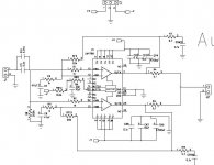
that is the function Rsn1 and Csn1/ Rsn2 and Csn2 in Page 6 Fig3?
and what is the effect of Ci1/Ci2 ?if i assume it will be short for high frequency, the over all gain will be larger, and less gain in L.F., so if i lower the capacitance(or remove the capacitor), will the gain be constant.
i am plainning to construct it as parallel.
thanks

 once my samples arrive. My plan is to build a nice set of amps for HT which can be coupled to a NAD decoder.
P2p may be possilbe if the leads are bent in such a way that you would have more open space where the pins are soldered to the wire. basicallyall of the outward pins are made at a 90 degree angle. then every other one of the inner pins is bent. then every other on of the top pins is bent a second time in a differnt place, allowing room on each side of the pin, and 4 rows of pins instead of 2.
All right then, maybe tagboard style, with just short wires to the pins (no components on the pins itself) and all components on a separate matrix (no board at all) - except maybe the feedback resistor and decoupling caps, which could be direct mounting, eh?
Actually have to see the chip. If there is no other way except PCB we will have to get some PCBs made. As per the eval board pattern, maybe...
The 4781 is even more interesting. 3 amps in one package of the same size as 4780!!! That will be a lot of fun.
Actually have to see the chip. If there is no other way except PCB we will have to get some PCBs made. As per the eval board pattern, maybe...
The 4781 is even more interesting. 3 amps in one package of the same size as 4780!!! That will be a lot of fun.
I had a little trouble finding the zipped files. Here is the link for anone interested.
http://www.national.com/appinfo/audio/0,1819,968,00.html
http://www.national.com/appinfo/audio/0,1819,968,00.html
I wouldn't cout out P2P just yet. Many pins are NC and can just be broken off, and there are many pins repeated, such as V- and V+, only one of each must be connected and the others can be broken off (bend them up and down a few times and they'll snap at the base like they weren't even there).
That should get rid of much of the clutter and make it much easier to P2P. I'm going to give it a try, see how it goes, but I'm guessing it's very doable.
That should get rid of much of the clutter and make it much easier to P2P. I'm going to give it a try, see how it goes, but I'm guessing it's very doable.
JoeBob said:I wouldn't cout out P2P just yet. Many pins are NC and can just be broken off, and there are many pins repeated, such as V- and V+, only one of each must be connected and the others can be broken off (bend them up and down a few times and they'll snap at the base like they weren't even there).
That should get rid of much of the clutter and make it much easier to P2P. I'm going to give it a try, see how it goes, but I'm guessing it's very doable.
actually.. no.. you can't snap off the repeated pins.. they are there for a reason.. becasuse a single pin can't supply the required current...
What's probably the bottleneck for the current is the wires inside the IC and not the pins on the outside, so if you've got two pins right next to each other (as is often the case on this chip) I am resiously doubting that the pin from the chip can't handle the current needed for a whole couple of milimeters and that the second pin next to it is needed.
Sure, maybe more than one should be connected, but I won't feel bad if one suply pin is hard to reach or connect power to and I just break it off.
Also, there are 7 pins that a NC and are easily snaped off, reducing 25% of the pins on the chip. So it doesn't look that hard to me.
Sure, maybe more than one should be connected, but I won't feel bad if one suply pin is hard to reach or connect power to and I just break it off.
Also, there are 7 pins that a NC and are easily snaped off, reducing 25% of the pins on the chip. So it doesn't look that hard to me.
- Status
- This old topic is closed. If you want to reopen this topic, contact a moderator using the "Report Post" button.
- Home
- Amplifiers
- Chip Amps
- anybody tried a LM4780?