
OK guys,
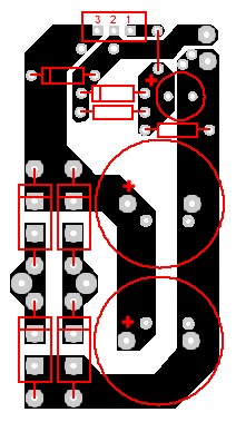
Since it became one of the main topics here these days, here is the possible basic layout for TO-220 packaged LM338/LT1083/LT1084 based regulator.
I honestly think one layer will be enough here. However, I would include a silk screen. It brings the feel of high-end… Ok, it makes soldering more convenient.
Diodes can be axial ones like SB560 or TO-220 ones like MUR860.
Heatsinks could be like some of these:
http://www.thermaflo.com/bin/stamps...+Board+Level+Products&SortBy=V4&NumPerPage=v4
(I am not affiliated with this manufacturer; please, post another link if you find it more useful to communicate over.)
One bigger heatsink can be used for both regulators but the regulators themselves should be isolated then.
Additional input and output bypass caps, one more protection diode and slow start circuit (which IME influences the things sonically – some might remember one a few months old twilight zone thread on this topic) are planned to be added.
You might post observations, objections and wishes for changes. Once the layout is finished, and someone(s) is/are ready to organize the fabrication and shipping, I will forward the file to him/her. I might order a couple of samples as well.
Pedja
Since it became one of the main topics here these days, here is the possible basic layout for TO-220 packaged LM338/LT1083/LT1084 based regulator.
An externally hosted image should be here but it was not working when we last tested it.
I honestly think one layer will be enough here. However, I would include a silk screen. It brings the feel of high-end…
Ok, it makes soldering more convenient.Diodes can be axial ones like SB560 or TO-220 ones like MUR860.
Heatsinks could be like some of these:
http://www.thermaflo.com/bin/stamps...+Board+Level+Products&SortBy=V4&NumPerPage=v4
(I am not affiliated with this manufacturer; please, post another link if you find it more useful to communicate over.)
One bigger heatsink can be used for both regulators but the regulators themselves should be isolated then.
Additional input and output bypass caps, one more protection diode and slow start circuit (which IME influences the things sonically – some might remember one a few months old twilight zone thread on this topic) are planned to be added.
You might post observations, objections and wishes for changes. Once the layout is finished, and someone(s) is/are ready to organize the fabrication and shipping, I will forward the file to him/her. I might order a couple of samples as well.
Pedja
matjans said:maybe you could include a trimpot footstamp for Vadj so voltage can be set exactly. I don't think carlos will object to this suffestion
No.
Pedja, another suggestion: if you rotate the heatsinks and regs by 90º to the extremes of the PCB, people could use whatever heatsink they like (bigger), even if it goes out of the board.
The "grounds" would be facing each other, and more space to bypass before the regs and after the regs (with film caps).
Of course this is optional, it's just that I always think of everything and my PCBs are usually full of holes.
more space to bypass before the regs and after the regs (with film caps).
you only want to use a bypassfilm/ceramic on the regulators inputpin.....
Have been thinking about that already and it can be done. It will make certain but still acceptable compromises. Though the regulators, at least if taken from the same batch, should have sufficiently equal voltages, assuming usage of 1% resistors.matjans said:maybe you could include a trimpot footstamp for Vadj so voltage can be set exactly. I don't think carlos will object to this suffestion
and suggestion is spelled with 2 g's, not f's...
Ahem, err… uhm...carlosfm said:Pedja, another suggestion: if you rotate the heatsinks and regs by 90º to the extremes of the PCB, people could use whatever heatsink they like (bigger), even if it goes out of the board.
The "grounds" would be facing each other, and more space to bypass before the regs and after the regs (with film caps).
Of course this is optional, it's just that I always think of everything and my PCBs are usually full of holes.
 This spells new layout? It might not be clear instantaneously, but when it comes to solve a few another issues, it might appear with this idea the designing is at the start again. If someone else wants to try, it is fine with me, but at this moment I do not have a time to check it.
 Generally, supply boards can be made as single units without heatsinks too, so one board would be needed for the + and second for the – half. This would give the user complete freedom considering used heatsinks. Or the same heatsink used for power ICs could be used for the supply too. At the other side I just liked the idea of compactness. In fact, the dimensions of the board itself are not very small, but everything is there. As I’ve said previously, if someone needs, can use one larger heatsinks for both regulators, space behind the regulators should be enough, eventually I can move the regs a bit further (of course, shown protection diodes must find some other places).
Actually, I’ve never used them either on the input or the output. But despite of the fact the reservoir caps are made of two half sized paralleled units, these are still huge enough to make a small input bypass cap idea worth to try. As about the output bypass cap, the idea is to make this board usable even if it is not next to an amp chip/board.tbla said:you only want to use a bypassfilm/ceramic on the regulators inputpin.....
But more important than all this is that I don’t see much reason to proceed with this as long as we don’t have someone ready to deal with the organization issues.
Pedja
Pedja said:
But more important than all this is that I don’t see much reason to proceed with this as long as we don’t have someone ready to deal with the organization issues.
Pedja
Quite right. Doesn't seem like the interest level is there right now. Hope I didn't take too much of your time.
At any rate, I ordered stuff to make the discrete version. Only a bit more complicated than using LM regulators. Digikey didn't have BD 911/912 so I ordered MJL3281/1302. Any reason those wouldn't work?
Sheldon
And a somewhat related question: I'm also trying the jfet buffer. Couldn't find 2sk170 but did find some 2sk 369. Any reason those wouldn't do?
Thanks in advance.
Sheldon said:
Doesn't seem like the interest level is there right now.
I for one am very interested in Regulator PCBs, but have far too little time at the moment to get involved with organising production
 . It would be great if someone could take this onboard - I'd certainly be prepared to pay for some quality boards. Failing that its back to good old breadboard .
These are the expensive, ten times higher Ft units than BD911/912 (hFE vs Ic is also significantly better). Hence they could be better, but no idea if you can get into troubles because of this or not. Anyway, you can use something quite mundane and cheap like 3055/2955.Sheldon said:At any rate, I ordered stuff to make the discrete version. Only a bit more complicated than using LM regulators. Digikey didn't have BD 911/912 so I ordered MJL3281/1302. Any reason those wouldn't work?
No.I'm also trying the jfet buffer. Couldn't find 2sk170 but did find some 2sk 369. Any reason those wouldn't do?
Pedja
Let’s clarify “the conditions”
It is needed some one or some ones able and ready to, once the board is finally designed, organize the fabrication and shipping.
The price of the board normally would include the fabrication costs and shipping costs with some safety margin for possible failures. The price should include also certain compensation for the time and effort invested by those who will deal with this. It would be nice if some percent could be contributed to the diyAudio site.
As long as this is the one time and only one time offer to the diyAudio community and not someone’s business, and as long as the contributors are known and recognized, I ask nothing for myself.
Pedja
My Input Buffer/ Regulated PS
I've got no time to organize a group design or buy, but I wouldn't mind if you all used my design for an input buffer and regulated PS (for DIY use, not commercial use). If not it could be another starting point or point of discussion. Note- this is a low power regulated PS for the input stage only, I used chips that have a 300-500 mA rating, but which are ultra low noise. I've made a board and it works fine (with a few errors in hole sizes and jumpers becuase its a single level board) with a slight turn on and of thump that you will find happens when you regulate the input buffer as the regulators turn on and off. My buffer is actually a differential receiver for a balanced input, but an opamp buffer could be used instead. I've used trimpots so you can easily adjust the output voltage to whatever you want.
Full information on the the GC here and on my web page.
prior thread on buffer.
Schematic
Bottom of Board (that's a dime pictured).
Top of Board
I've got no time to organize a group design or buy, but I wouldn't mind if you all used my design for an input buffer and regulated PS (for DIY use, not commercial use). If not it could be another starting point or point of discussion. Note- this is a low power regulated PS for the input stage only, I used chips that have a 300-500 mA rating, but which are ultra low noise. I've made a board and it works fine (with a few errors in hole sizes and jumpers becuase its a single level board) with a slight turn on and of thump that you will find happens when you regulate the input buffer as the regulators turn on and off. My buffer is actually a differential receiver for a balanced input, but an opamp buffer could be used instead. I've used trimpots so you can easily adjust the output voltage to whatever you want.
Full information on the the GC here and on my web page.
prior thread on buffer.
Schematic
An externally hosted image should be here but it was not working when we last tested it.
Bottom of Board (that's a dime pictured).
An externally hosted image should be here but it was not working when we last tested it.
Top of Board
An externally hosted image should be here but it was not working when we last tested it.
hmmmm...
Boredom causes people to do odd things. And I was bored this afternoon.
I've never tried to design a PCB before but found myself messing around with it this afternoon anyhow. I only got this far using Pedja's work (including PCB design) and some other posts (carlosfm) and as far as I know this could be absolute junk. I was trying to keep the reg at the edge and leave a little room to put those small caps Carlos seems so fond of, and as close to the reg as I could put them. Also room for both protection diodes.
This is just one side of course.
what needs fixin? (or, should I just not bother any more?)
C
Boredom causes people to do odd things.
And I was bored this afternoon.I've never tried to design a PCB before but found myself messing around with it this afternoon anyhow. I only got this far using Pedja's work (including PCB design) and some other posts (carlosfm) and as far as I know this could be absolute junk.
I was trying to keep the reg at the edge and leave a little room to put those small caps Carlos seems so fond of, and as close to the reg as I could put them. Also room for both protection diodes.This is just one side of course.
what needs fixin? (or, should I just not bother any more?)
C
C,
I am trying to figure the orientation of the regulator… is it mounted downward or do we see the board looking from below? Besides, something like that can be done with that notice I’d rather try to avoid jumpers and I'd put current set resistor (that on pin 2) closer to the chip than diodes.
Pedja
I am trying to figure the orientation of the regulator… is it mounted downward or do we see the board looking from below?
Besides, something like that can be done with that notice I’d rather try to avoid jumpers and I'd put current set resistor (that on pin 2) closer to the chip than diodes.Pedja
Pedja: the heat sink goes off the top, and pins are marked. I think that only leaves one way for the reg to mount? I actually did this in a graphics program and started with your diagram, so it's however you had it, rotated 90 degrees clockwise.
Without going double sided or using a jumper, I was unable to get the reg at the edge of the board. It wouldn't be much to switch to a double sided layout.
As to the resistor location, that shouldn't be difficult at all. Considering I neglected to leave room for a trimpot in that spot anyhow. . .
As I said, I've never done PCB design - this stuff is only a rather new hobby of mine. So I'm a little surprised that's all you have to say.
Double sided I think cleans a few things up nicely, so may be worthwhile regardless. Since I suspect I'll be bored for some days to come, who knows. Just figured I'd not keep tweaking if the first try was a total flop.
C
Uhhh...
Yes Pedja, the reg is reversed...
And to avoid jumpers the trace that goes po pin 2 can pass behind the reg.
The PCB should have the two regs, the less boards you have to mount on the case, the better.
Anyway, it's almost copy-paste to do it.
*** EDIT***
Oh it's just one side, forget it.
Yes Pedja, the reg is reversed...
And to avoid jumpers the trace that goes po pin 2 can pass behind the reg.
The PCB should have the two regs, the less boards you have to mount on the case, the better.
Anyway, it's almost copy-paste to do it.
*** EDIT***
Oh it's just one side, forget it.
Any better? I'm not sure if the trace to pin 3 is too thin on the one (right side), but figured I'd see if I could mirror the output placement while keeping component position the same between the two boards. Except for the two small value caps (not pictured but allowed for) it does that. The idea there was to allow these to share a heatsink (either side, or along one side) and perhaps still keep leads short. Though the output should probably be to the outside edges if this were a single PCB?
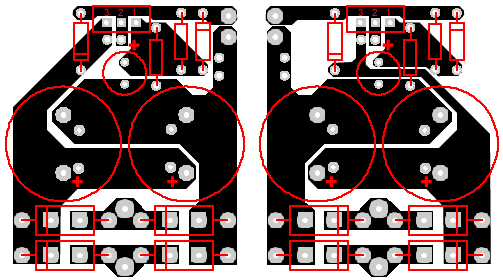
Also, I see now that I did flip the reg pins relative to Pedja's PCB design, though I do believe I got all the components to the right places despite that. So, this should be a "bottom" view of things (I dug out the spec sheet and double checked it, so I am sure to have it all wrong now).
I would NOT be able to do this stuff without reading all the posts (even the fights ) here... but PCB layout seems mostly to be a design puzzle, and that's not so far off from my areas of experience.
C
Also, I see now that I did flip the reg pins relative to Pedja's PCB design, though I do believe I got all the components to the right places despite that. So, this should be a "bottom" view of things (I dug out the spec sheet and double checked it, so I am sure to have it all wrong now).
I would NOT be able to do this stuff without reading all the posts (even the fights
) here... but PCB layout seems mostly to be a design puzzle, and that's not so far off from my areas of experience.C
Now I might sound discouraging, but I liked better the previous version.
There are a few general demands about physical organization: AC at one side, outgoing DC at the other, DC closer to the amp chips (with regulators yet positioned thus to make possible the adequate heatsinking)...
Now, about the routing on the board itself, else than it should respect the previously said things, two routes are important, and this is applicable to practically all the 3 pin adjustable devices. One is that the current set resistor path shouldn’t be shared with the output loop path or it worsens the load regulation (someone care to connect current set resistor directly to the case/tab?), and second, the sensing point goes as close as possible to the load, which in this case practically means it goes at the output of the board where it could be connected to the reservoir caps minus side. The thing I also think is not bad to practice is to mount resistors in parallel with the reg/heatsink and thus to ensure the same temperature at their ends.
Pedja
Pedja said:Now I might sound discouraging, but I liked better the previous version.
Nothing discouraging at all. As long as you (or anyone) is willing to share and help me along, I'll gladly soak it up. If the result is something others can use, all the better. You've given me some things to ponder (largely to make sure I understand what you're saying).
Thanks for the feedback.
C
Watching eagerly!
Hey C-
You mentioned
"If the result is something others can use, all the better."
Well I am watching this thread eagerly. I applaud you for giving the design a shot and being smart enough to learn from the more experienced members such as Pedja and Carlos.
Please keep up the good work and great attitude, I for one will appreciate the end results.
I love pre-made PCB's because they are SO much cleaner than p2p wiring or perf boards.
Thanks, Troy
edit: Oh yeah, thanks Pedja and Carlos for helping!!
- Status
- This old topic is closed. If you want to reopen this topic, contact a moderator using the "Report Post" button.
- Home
- Amplifiers
- Chip Amps
- Any interest in GC input buffer and power supply regulator pcb's?