you get +3db for that commentyou could even use 1/2 inch plywood like Bill Fitz does

Now a quick word about CON PAR and EXP since you said you were still a bit confused.
Any of these can be used for a duct that has a constant cross sectional area (same area at both ends). In cases where cross sectional area does change it does matter which you choose.
PAR describes the proper mathematical construct for a duct that has two parallel side walls and two side walls that are not parallel (expanding or decreasing cross sectional area). This is almost always how bass horns are built.
CON describes a conical horn, with all 4 sides expanding (or a round horn). This is almost always how Synergy and Unity horns are built.
EXP describes an exponential horn. You have to use curved walls to build this properly, it's almost never done.
NOW like TB46 mentioned you can play with these concepts a bit. You can form an exponentially shaped flare with a bunch of PAR segments. It would take an infinite number of PAR segments to track the exponential shape with 100 percent accuracy, but that type of accuracy is not really necessary.
Let's see if I can copy and paste most of a post by LTD02 with pictures intact from avsforum. EDIT - Hmm, it worked, I'm surprised. I didn't think the pics would show.
So how important is all of this? If you want to make 100 percent sure you sim represents real world mathematical constructs as closely as possible, and if you want your schematic drawing to accurately tell you the net volume, and if you want the Horn Data export chart to accurately reflect something that can actually be accurately folded and built, then it's important. Otherwise, you can fudge things as much as you want.
Any of these can be used for a duct that has a constant cross sectional area (same area at both ends). In cases where cross sectional area does change it does matter which you choose.
PAR describes the proper mathematical construct for a duct that has two parallel side walls and two side walls that are not parallel (expanding or decreasing cross sectional area). This is almost always how bass horns are built.
CON describes a conical horn, with all 4 sides expanding (or a round horn). This is almost always how Synergy and Unity horns are built.
EXP describes an exponential horn. You have to use curved walls to build this properly, it's almost never done.
NOW like TB46 mentioned you can play with these concepts a bit. You can form an exponentially shaped flare with a bunch of PAR segments. It would take an infinite number of PAR segments to track the exponential shape with 100 percent accuracy, but that type of accuracy is not really necessary.
Let's see if I can copy and paste most of a post by LTD02 with pictures intact from avsforum. EDIT - Hmm, it worked, I'm surprised. I didn't think the pics would show.
here is the idea put another way. we want to approximate the exponential curve with straight sections. can it be done? yes. it works "good enough".
this is the horn we want to model (just an example, not to scale or anything):

this is approximating the exponential curve with straight sections (illustrative example, not to any scale). straight boards, of course, create straight segments that are technically modeled with "par" in hornresp. but by going the other way, straight sections can be used to create an exponential flared horn. if that is what one wants.

it is the same concept as this, but with fewer straight lines, so the curve isn't quite as accurate, but still "good enough":

some folks may not believe that curve comes from straight lines. if you haven't seen this before, give it a shot. it is fun to draw it out.
So how important is all of this? If you want to make 100 percent sure you sim represents real world mathematical constructs as closely as possible, and if you want your schematic drawing to accurately tell you the net volume, and if you want the Horn Data export chart to accurately reflect something that can actually be accurately folded and built, then it's important. Otherwise, you can fudge things as much as you want.
you get +3db for that comment
Probably more accurately -3db. Panel flex equates to losses, not gains. It takes a lot of bracing to make the 1/2 inch material equivalent to 3/4 inch material, and using a lot of bracing kind of defeats the purpose of trying to use less material. But it is an option.
Oops, forgot to source LTD02's post. All credit due and all that. SubMaximus -- A Large Front-Loaded Horn for UXL18 and Stereo Integrity HT 18" - Page 2 - AVS | Home Theater Discussions And Reviews
This is already taking too long and I haven't even discussed actual folding yet...
This is already taking too long and I haven't even discussed actual folding yet...
LOL....thanks for the links. I had been reading those lately anyways. LTD also designs a large single 21 Sw115 horn that never got built but reminded me of the similarities of my design.
And regarding weight this cabinet is going to be heavy regardless. 12mm is not going to happen for me. I have used lots of different thicknesses and when using an 18 I will only use 18mm or thicker. I would never trust 12mm with a 21" driver. bracing or not I dont trust 12mm.
Regarding the curves I do understand that. I learned about the advanced way of doing from when I was reading the flat to 30hz thread.
Also for my design to have a forth section in a horn will 5 be better?
I will just divide the length and volume going from 2 to section 3 into 2 parts. And make that section 4 and section 5.
And now to get this horns size down to 628l or less will be a balancing act for me. TB46's original was about 590l. But as I said tuned much higher.
While I also think it would be great that people would even want to built this design but it is not a concern. I will use 24" wide external dimensions. So 22.5" for internal width. If the 21" fits in Ricci's horn with this dimension it will work for me.
I dont want to go to tall/wide because I will most likely place a speaker on top of the subwoofer cabinet. Too high and it becomes very difficult for me to lift the speaker. So 48" is max.
And I feel if you really were worried pack space build the Othorn. I will be using just a pair for anything I want to do.(Cinema)
So all very helpful information. And in case you dont know I am on a LOT of forums. So I have been reading quite a bit for sometime. I just try and take onboard what I can and what pertains to me or my design. Some times after projects are done I have a partial data dump and have o relearn when I come back to things.
Anyways will look at adding at least one more section of a horn to my design.
Ok, well I don't know what you know, so I'm trying to hit all the major bases. You said you don't know how to fold or reverse engineer so I thought you didn't know most of this stuff.
I only have a couple more posts on folding, tips and tricks to make things easier and a couple of different ways to go about it.
By the way, if you didn't already know, Brian Steele has an autofolding spreadsheet, the spreadsheet does the fold for you. I'm not sure if it's only for tapped horns or if it also applies to flh too, if you aren't aware of it you can find the thread and maybe PM him about it. Having the computer do the fold is an option, and even if his spreadsheet is only for tapped horns you could probably trick the spreadsheet into doing a flh fold anyway by including the rear chamber volume into the horn flare somehow (maybe specify a really big throat chamber instead, but use it as a rear chamber). Not sure how flexible his spreadsheet is, or if it will accept any chambers or weird flare shapes at all. You can check on that, I like to fold by hand.
BUT just like the soho Sketchup fold method, I'm not sure how his spreadsheet deals with putting the segment markers where they are supposed to be, the problem described in post 180. Always be aware of that issue. If you are good at excel maybe you can write up your own horn folding spreadsheet.
Using more segments will allow you to have a more detailed flare shape, for example you could have a more exponential flare shape if that's what you wanted. But it doesn't have to have a really detailed flare shape, a lot of tapped horns, and Bill's THT (from what I can tell) are just a single flare rate. The expo horn shape is what's going to give you that flh rising response. It's possible to kill off that rising response by playing with the flare shape and making the mouth small, but that's probably not a good idea. The flare shape is up to you and whatever you work out in Hornresp. Use as many segments as you want. Start with the max available amount and get rid of them if it doesn't appear that you need them.
Last edited:
I guess keeping the mouth and chamber near each other would work out best.
I remember his spread sheet and could never get it to work with any of my simulations which were FLH's and other odd ball designs.
I am now just trying to get the size down to 625 while maintaining extension and SPL and adding in the 4 section of the horn.
I remember his spread sheet and could never get it to work with any of my simulations which were FLH's and other odd ball designs.
I am now just trying to get the size down to 625 while maintaining extension and SPL and adding in the 4 section of the horn.
By the way, if you didn't already know, Brian Steele has an autofolding spreadsheet, the spreadsheet does the fold for you. I'm not sure if it's only for tapped horns or if it also applies to flh too, if you aren't aware of it you can find the thread and maybe PM him about it. Having the computer do the fold is an option, and even if his spreadsheet is only for tapped horns you could probably trick the spreadsheet into doing a flh fold anyway by including the rear chamber volume into the horn flare somehow (maybe specify a really big throat chamber instead, but use it as a rear chamber). Not sure how flexible his spreadsheet is, or if it will accept any chambers or weird flare shapes at all. You can check on that, I like to fold by hand.
The spreadsheet works only for the SS15 type fold, though the techniques used can be deployed for other spreadsheets to design other folded horns. The hardest part of putting it together was finding a simple programmatic way to determine each panel's location wrt other panels in the folded horn .
Oh, and it handles the segment markers quite well. It even allows you to shift one of the markers if you want to.
I'm trying to simplify it even further, because it still contains a lot of variables to play with, which makes the sim-folding take a bit longer than it should.
On to actual folding. Like I said, it's wise to design and fold at the same time, at least have a really good idea what the fold is going to look like while you are simulating. Josh already described this, and I'm pretty sure it's how he folded his horns. Sim and fold at the same time.
I'm not sure exactly how he did his, but here's a good way to approach this method. After a couple of minutes playing with the simulator you should have a pretty good idea how big the horn is going to be. Add 15 - 30 percent on top of the net volume reported by Hornresp, choose the external dimensions and you're off. Draw the dimensioned box shape in Sketchup. Then get the Hornresp Horn Data export info and start drawing in the last couple of flares from the mouth to the back of the box. At this point you will have something that looks like this in Sketchup.
At this point, figure out where the rest of the horn path and chamber could go, there's a bunch of different options but only a few of them will give you the horn length you need and put the driver access panel where you want it.
When you have something that you think will work, draw it in. Use Sketchup to find the segment lengths, cross sectional area at the bends and the chamber volume. If it's close to the original sim you are on the right track. Take this new info and run the sim of the drawing you just drew.
If the new sim doesn't look good change the drawing a bit, going back and forth from the sim to the drawing until you have a drawing that sims well. Sometimes it doesn't work out and you have to choose a different layout, so scrap it and go back to the original drawing as shown in the pic above and try a different layout.
If you try a few and nothing works you might have to change the external dimensions (not the overall volume, but just the shape of the rectangle). It shouldn't take too long to come up with something acceptable. I think Josh spent months doing this, but he had a huge number of folds, he was using Akabak to account for them all, and he was pretty serious about getting the best performance he could. So this can be fairly simple or it can take months, it's up to you and the goals you set for yourself.
This is a good method because you don't have to mess around trying to make a sim fit into a perfect rectangle, the rectangle is there and you are trying to put a sim into it that will work. The dimensions are fixed from the start so there's no messing around in Hornresp and increasing the volume. As you found, it's very hard to keep the volume steady, a little bigger always looks better and before you know it the sim is several hundred liters bigger than your original goal. There's none of that happening with this folding method you choose the dimensions first and make the sim fit into it.
At this point the simulation part is easy. The problem comes when you try to fold up what you sim'd into a cabinet you can live with. Sometimes you find that the length ends up a little longer or shorter than you were trying to go or you find that the fold won't fit with the amount of area you had entered at your major areas of the horn or you run into logistical problems like accessing the driver or simple things like where to put the terminals. If you allow the horn to dictate the cab it is a bit easier than if you start with a dimensioned cab and put the horn into that space. In that case you'll find that in most cases your cabinet design ends up veering off a bit from the ideal simulation you wanted to match, but at the end of the day a little variation from the sim isn't a deal killer and you probably would never notice.
I'm not sure exactly how he did his, but here's a good way to approach this method. After a couple of minutes playing with the simulator you should have a pretty good idea how big the horn is going to be. Add 15 - 30 percent on top of the net volume reported by Hornresp, choose the external dimensions and you're off. Draw the dimensioned box shape in Sketchup. Then get the Hornresp Horn Data export info and start drawing in the last couple of flares from the mouth to the back of the box. At this point you will have something that looks like this in Sketchup.
An externally hosted image should be here but it was not working when we last tested it.
At this point, figure out where the rest of the horn path and chamber could go, there's a bunch of different options but only a few of them will give you the horn length you need and put the driver access panel where you want it.
When you have something that you think will work, draw it in. Use Sketchup to find the segment lengths, cross sectional area at the bends and the chamber volume. If it's close to the original sim you are on the right track. Take this new info and run the sim of the drawing you just drew.
If the new sim doesn't look good change the drawing a bit, going back and forth from the sim to the drawing until you have a drawing that sims well. Sometimes it doesn't work out and you have to choose a different layout, so scrap it and go back to the original drawing as shown in the pic above and try a different layout.
If you try a few and nothing works you might have to change the external dimensions (not the overall volume, but just the shape of the rectangle). It shouldn't take too long to come up with something acceptable. I think Josh spent months doing this, but he had a huge number of folds, he was using Akabak to account for them all, and he was pretty serious about getting the best performance he could. So this can be fairly simple or it can take months, it's up to you and the goals you set for yourself.
This is a good method because you don't have to mess around trying to make a sim fit into a perfect rectangle, the rectangle is there and you are trying to put a sim into it that will work. The dimensions are fixed from the start so there's no messing around in Hornresp and increasing the volume. As you found, it's very hard to keep the volume steady, a little bigger always looks better and before you know it the sim is several hundred liters bigger than your original goal. There's none of that happening with this folding method you choose the dimensions first and make the sim fit into it.
Last edited:
Oh, and it handles the segment markers quite well. It even allows you to shift one of the markers if you want to.
That's clever and extremely useful. I like accuracy.
You know you could make a lot of money if you made one that was a bit more flexible and could handle other fold styles and include chambers too, right? People don't seem to like folding.
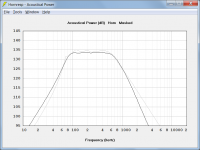
(In actuality it would be far more useful if it was a constant voltage and excursion limited graph rather than constant power and excursion. David any chance of that happening or that type of graph being added?)
Hi Josh,
Capturing the Maximum SPL chart and then comparing the result against the Acoustical Power chart calculated at different values of Eg, should give you what you want, without the need for another chart in Hornresp.
To illustrate, the attached screenprint shows the default record Maximum SPL response (grey trace) compared against the Acoustical Power response calculated at Eg = 30 volts (black trace). The Acoustical Power response exceeds the specified displacement / power limits at those frequencies where the grey trace is lower than the black trace. As you can see, for a constant input of 30 volts, Xmax is exceeded up to about 60Hz, and Pmax is exceeded (just slightly) from about 600Hz to 1000Hz.
The Acoustical Power response can be calculated for any given value of Eg, and the captured Maximum SPL response quickly superimposed by pressing F4.
Kind regards,
David
Attachments
Thanks for the reference to the Thuras patent in Post #152.
Hi Oliver,
You should be thanking Bjørn for providing the reference, rather than me
") .
.Kind regards,
David
Ok, last folding post I think.
So because someone did the math, we know that any PAR segment that is folded back onto itself forms a perfect rectangle (as long as it's built with 2 parallel sides). Also, and portion of a PAR segment that is folded back onto itself will form a perfect rectangle in the folded part. Here's an example. None of this is to scale of course. Top pic, unfolded PAR segment. Middle pic, same PAR segment folded in half. Bottom pic, PAR segment only partially folded, forming a perfect rectangle in the folded part. EDIT - Oops, that last one isn't open at the end. I'm not going to change it now, just pretend it's open on the big end like the other two.
Even by itself this is insanely useful but wait there's more.
If we look at the single unfolded PAR segment above and add the cross sectional area at the beginning and end of the segment together and divide by the desired enclosure depth and add .75 inch to account for the divider board, we know the exact cross sectional area AND width AND depth of the folded segment. And if we take the unfolded segment length and divide by 2, we know the approximate (but very close) length of the folded segment.
So we know that we can fold any given PAR segment, and with a few details we know it's exact cross sectional area when folded, know the exact depth and width of the folded segment, and have a very close estimate of the folded length (subject to minor change due to centerline angle and advanced centerline folding method but still really really close).
Even by itself this is insanely useful but wait there's more.
If we fold up a horn so that's it's just a bunch of rectangles, and we already know the dimensions of the rectangles, the fold is as simple as stacking blocks. The rear chamber shape doesn't matter, it's flexible, so it can fit wherever it needs to go. The only thing to be mindful of during the simulation is that the segment markers go in the right spots, and the resulting rectangles made from folded PAR segments results in blocks with dimensions that form a rectangle when stacked.
Any or all of these tips and tricks can be used, and a horn can be folded exclusively using this method if desired, or these tips and tricks can be used separately with other fold methods, like the method described in the previous folding post. The only real issue with this method is that it results in a whole lot of 180 degree bends.
Anyway, using these guidelines, a simple single fold horn with no chamber (tl or tapped horn) can be folded with a high degree of accuracy in a matter of minutes. Adding chambers and more segments and flare rate changes takes a few more minutes. And working it all out with perfect accuracy, advanced centerline folding method, etc (if desired) can take longer, but even if you don't bother with all that it will still be pretty close. (I always take the time to get as accurate as possible if I'm going to actually take the time and money to build something.)
So we have a folded PAR segment, the only thing left is to figure out where the divider board goes. Using the Hornresp Horn Data export info we know where the divider board starts, and with one more piece of data (length vs csa at any other point in the segment) we know the angle of the board.
That pic shows that if we know the dimensions of the folded segment, the place where the divider board starts, and one additional data point on the divider board location, we can just draw it right in. The only remaining question is how long the divider board is. Even just drawing it in by eye and ending it so it looks like it expands going around the bend is probably close enough, but you can get a lot closer using the Hornresp Horn Data export info and taking measurements of the drawing in Sketchup.
So it's all really pretty simple. Extreme accuracy takes a lot of time, especially if you want to use advanced centerline method, but the concepts are all really simple and there are a bunch of tips and tricks to help and make things a lot easier. You can get really close really fast using these concepts.
Hopefully this helps.
So because someone did the math, we know that any PAR segment that is folded back onto itself forms a perfect rectangle (as long as it's built with 2 parallel sides). Also, and portion of a PAR segment that is folded back onto itself will form a perfect rectangle in the folded part. Here's an example. None of this is to scale of course. Top pic, unfolded PAR segment. Middle pic, same PAR segment folded in half. Bottom pic, PAR segment only partially folded, forming a perfect rectangle in the folded part. EDIT - Oops, that last one isn't open at the end. I'm not going to change it now, just pretend it's open on the big end like the other two.
An externally hosted image should be here but it was not working when we last tested it.
Even by itself this is insanely useful but wait there's more.
If we look at the single unfolded PAR segment above and add the cross sectional area at the beginning and end of the segment together and divide by the desired enclosure depth and add .75 inch to account for the divider board, we know the exact cross sectional area AND width AND depth of the folded segment. And if we take the unfolded segment length and divide by 2, we know the approximate (but very close) length of the folded segment.
So we know that we can fold any given PAR segment, and with a few details we know it's exact cross sectional area when folded, know the exact depth and width of the folded segment, and have a very close estimate of the folded length (subject to minor change due to centerline angle and advanced centerline folding method but still really really close).
Even by itself this is insanely useful but wait there's more.
If we fold up a horn so that's it's just a bunch of rectangles, and we already know the dimensions of the rectangles, the fold is as simple as stacking blocks. The rear chamber shape doesn't matter, it's flexible, so it can fit wherever it needs to go. The only thing to be mindful of during the simulation is that the segment markers go in the right spots, and the resulting rectangles made from folded PAR segments results in blocks with dimensions that form a rectangle when stacked.
Any or all of these tips and tricks can be used, and a horn can be folded exclusively using this method if desired, or these tips and tricks can be used separately with other fold methods, like the method described in the previous folding post. The only real issue with this method is that it results in a whole lot of 180 degree bends.
Anyway, using these guidelines, a simple single fold horn with no chamber (tl or tapped horn) can be folded with a high degree of accuracy in a matter of minutes. Adding chambers and more segments and flare rate changes takes a few more minutes. And working it all out with perfect accuracy, advanced centerline folding method, etc (if desired) can take longer, but even if you don't bother with all that it will still be pretty close. (I always take the time to get as accurate as possible if I'm going to actually take the time and money to build something.)
So we have a folded PAR segment, the only thing left is to figure out where the divider board goes. Using the Hornresp Horn Data export info we know where the divider board starts, and with one more piece of data (length vs csa at any other point in the segment) we know the angle of the board.
An externally hosted image should be here but it was not working when we last tested it.
That pic shows that if we know the dimensions of the folded segment, the place where the divider board starts, and one additional data point on the divider board location, we can just draw it right in. The only remaining question is how long the divider board is. Even just drawing it in by eye and ending it so it looks like it expands going around the bend is probably close enough, but you can get a lot closer using the Hornresp Horn Data export info and taking measurements of the drawing in Sketchup.
So it's all really pretty simple. Extreme accuracy takes a lot of time, especially if you want to use advanced centerline method, but the concepts are all really simple and there are a bunch of tips and tricks to help and make things a lot easier. You can get really close really fast using these concepts.
Hopefully this helps.
Last edited:
How big does a 680l design need to be externally?
15 to 30 percent larger than the net volume reported on the Hornresp schematic. It depends on a lot of things but should be somewhere in that range.
What extension are you aiming for? You said home use, will it be music or movies mostly? Also I've read that low qts/strong drivers can be counterproductive in flh design, is there a way to work that out when designing the flh around a robust driver (which I'm under the impression the 21sw152 is) or would there be more optimal to use a 21" with lower moving mass and higher qts?
I really like sines folding, looks very simple and fast-forward.
I really like sines folding, looks very simple and fast-forward.
Last edited:
It's really hard to beat a driver you already own, especially when the the driver you already own is a high quality B&C and ballpark price for equivalent drivers that may or may not be slightly better is several hundred dollars. The driver he has is fine. Maybe not perfect, but it's more than adequate. To find the perfect driver you'd have to consult Leach's math, and it's really not even worth the bother, this driver is fine.
The design goal for me is to have very similar BW as the Othorn. I will be using this in very large rooms, gymnasiums and outdoors. This will never be used inside my home. I am building a much smaller setup for home. And at times I will use this in my backyard obviously with only about 200watts.What extension are you aiming for? You said home use, will it be music or movies mostly? Also I've read that low qts/strong drivers can be counterproductive in flh design, is there a way to work that out when designing the flh around a robust driver (which I'm under the impression the 21sw152 is) or would there be more optimal to use a 21" with lower moving mass and higher qts?
I really like sines folding, looks very simple and fast-forward.
My plan with the Othorns is to have a sub for cinema outdoors that has enough SPL and whatever extension. I could have gone the Ghorn route but I cant get the TC driver and the UXL I am not going to buy for other reasons. So when looking for high SPL I chose to get of the extension train at 25hz. That will be low enough and with a Hpass the design will still net a reasonable 20hz DB.
But what if I built a FLH around the same everything, what would that sound like?
And here we are.If I could I would love to also try the RCF 21N551. It appears to do even better in all my simulations compared to the SW152 in my designs. BUT BC is easier for me to buy and much cheaper. PLUS I have one already and it models very well.It's really hard to beat a driver you already own, especially when the the driver you already own is a high quality B&C and ballpark price for equivalent drivers that may or may not be slightly better is several hundred dollars. The driver he has is fine. Maybe not perfect, but it's more than adequate. To find the perfect driver you'd have to consult Leach's math, and it's really not even worth the bother, this driver is fine.
AND as JAG has stated once you have a decent simulation, the FLH design seems to work with a LOT of drivers with weaker motors or stronger ones. I would love to try the 18 Sound 21LW1400 also but I dont see the reason why when it costs not a lot different then the BC. So for me I will stick with the BC. And the 9601 costs me about 200 more dollars than the BC and offers not as much SPL.
Othorn looks to be 20 db down at 20 hz with the hpf in place, which is closer to "inaudible" than "reasonable". Any other content on the recording will mask the 20 hz content almost completely. The 560 liter flh I showed was about the same. Unless the design you are working on is tuned considerably lower, I'd say you are getting off the extension train at 30 hz and there's nothing of any note below that.
- Status
- This old topic is closed. If you want to reopen this topic, contact a moderator using the "Report Post" button.
- Home
- Loudspeakers
- Subwoofers
- Any good plans out for FLH's?