I'm going to agree that the excursion curve isn't going to move too much at all so I guess that isn't too much concern.
But unfortunately all the experimenting I've done so far with using peq instead of a hpf doesn't show much advantage. Once you notch out the offending excursion spike what you are left with doesn't leave much gain over a simple hpf.
If you don't use a sharp notch, bandwidth outside of the target gets affected adversely. If you do use a sharp notch you need 2 or 3 of them to clean up the whole excursion spike. And either way in the end I haven't been able to get much better results than a much simpler hpf can achieve.
I was thinking of this as something that may be useful with a FLH in relatively small spaces like homes or small venues where you may get enough of a lift below the modal region to get a bit of extra useful extension. I might have to give this a try if I ever get a chance. I doubt it would be worthwhile but who knows.
I wish you could edit posts here!
Let's try again...
Sensitivity and output at 120v which is equivalent to a little over 4kW maximum into the impedance minimums. No high pass. Free-space. Below that is the excursion associated with them under those conditions.
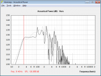
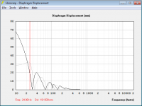
Now let's add some filters to the Othorn. A 4th order 90Hz BW low pass and a 23Hz 3rd order BW high pass. The HPF is what I used and recommend for the Othorn. We get the graphs below. The excursion with these filters and a 120v input is also shown. This works with the Othorn and I never had any problems.
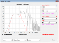
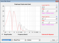
Now let's look at some filters for the FLH that had input parameters posted a few pages back. Again at the same 120v input level. The high pass needed is a little more aggressive due to the higher tuning of the FLH and the point at which excursion gets out of hand being somewhat higher in frequency. The LPF is the same. The HPF is a 27Hz BW 3rd order. This cuts the low end enough to keep the excursion reasonable with this much input power. As you can see by comparing the graphs there won't be much extra <50Hz deep bass from the FLH vs the Othorn in this case and any useful extra extension is filtered away by the HPF being set higher in frequency.
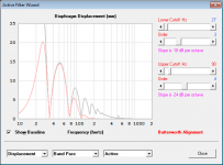
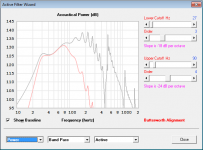
Ok so the FLH can take more power before running out of excursion at the first in band peak. We increase the input voltage from 120 to 165 volts in this next set of filtered graphs for the FLH in order to maximize the full bandwidth output. However at this point we are dumping double the power into the FLH over the Othorn with over 8kW required at the impedance minimums. Note that since the power is increased so are the excursion demands and now the 27Hz HPF used with a 120v input is not enough. It is moved up higher to 32Hz in order to keep the deep bass excursion under control. This results in not much more output than what we had before in the bottom octave of the FLH's bandwidth and a steeper overall roll off on the bottom.
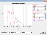
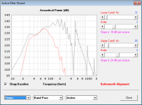
Remember that the FLH sim is about 30% larger than the Othorn, is tuned about 1/3rd octave higher and would require an amp rated for twice the power to make use of all of its potential driver excursion. However even after all of that the 25-50Hz octave output is nearly a dead heat between the two as shown in the sims. Obviously bass from 50-100Hz is critical as well and there the FLH will handily win so it should be the superior cab overall but you pay for this with increased size and weight. Now imagine what is going to happen when the FLH has the extra 30% in size advantage nullified? This is what I was trying to illustrate earlier is that some of the tradeoffs of the two horn types are that TH's get more output over about a 1 octave spread at the bottom of their useful bandwidth, when using the same cabinet size, but FLH's have a smoother, better behaved and more efficient second octave and on up in most cases. The distortion performance may be better as well. I'm not advocating for one or the other but from everything I've seen a properly designed TH will have superior headroom and sensitivity over an equivalent sized FLH in the bottom useful octave of their bandwidths.
Now let's look at max spl with an excursion and power limit. As we can see there is no advantage for the FLH from about 23Hz to around 50Hz. We can see from the above data that the FLH also has lower voltage sensitivity from about 30-50Hz as well. Obviously the FLH has clear advantage above that point. This is really the only point I was trying to make. 25-50Hz octave the max output is virtually a dead heat. I don't know how much more plainly this can be shown.
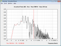
Let's try again...
Sensitivity and output at 120v which is equivalent to a little over 4kW maximum into the impedance minimums. No high pass. Free-space. Below that is the excursion associated with them under those conditions.


Now let's add some filters to the Othorn. A 4th order 90Hz BW low pass and a 23Hz 3rd order BW high pass. The HPF is what I used and recommend for the Othorn. We get the graphs below. The excursion with these filters and a 120v input is also shown. This works with the Othorn and I never had any problems.


Now let's look at some filters for the FLH that had input parameters posted a few pages back. Again at the same 120v input level. The high pass needed is a little more aggressive due to the higher tuning of the FLH and the point at which excursion gets out of hand being somewhat higher in frequency. The LPF is the same. The HPF is a 27Hz BW 3rd order. This cuts the low end enough to keep the excursion reasonable with this much input power. As you can see by comparing the graphs there won't be much extra <50Hz deep bass from the FLH vs the Othorn in this case and any useful extra extension is filtered away by the HPF being set higher in frequency.


Ok so the FLH can take more power before running out of excursion at the first in band peak. We increase the input voltage from 120 to 165 volts in this next set of filtered graphs for the FLH in order to maximize the full bandwidth output. However at this point we are dumping double the power into the FLH over the Othorn with over 8kW required at the impedance minimums. Note that since the power is increased so are the excursion demands and now the 27Hz HPF used with a 120v input is not enough. It is moved up higher to 32Hz in order to keep the deep bass excursion under control. This results in not much more output than what we had before in the bottom octave of the FLH's bandwidth and a steeper overall roll off on the bottom.


Remember that the FLH sim is about 30% larger than the Othorn, is tuned about 1/3rd octave higher and would require an amp rated for twice the power to make use of all of its potential driver excursion. However even after all of that the 25-50Hz octave output is nearly a dead heat between the two as shown in the sims. Obviously bass from 50-100Hz is critical as well and there the FLH will handily win so it should be the superior cab overall but you pay for this with increased size and weight. Now imagine what is going to happen when the FLH has the extra 30% in size advantage nullified? This is what I was trying to illustrate earlier is that some of the tradeoffs of the two horn types are that TH's get more output over about a 1 octave spread at the bottom of their useful bandwidth, when using the same cabinet size, but FLH's have a smoother, better behaved and more efficient second octave and on up in most cases. The distortion performance may be better as well. I'm not advocating for one or the other but from everything I've seen a properly designed TH will have superior headroom and sensitivity over an equivalent sized FLH in the bottom useful octave of their bandwidths.
Now let's look at max spl with an excursion and power limit. As we can see there is no advantage for the FLH from about 23Hz to around 50Hz. We can see from the above data that the FLH also has lower voltage sensitivity from about 30-50Hz as well. Obviously the FLH has clear advantage above that point. This is really the only point I was trying to make. 25-50Hz octave the max output is virtually a dead heat. I don't know how much more plainly this can be shown.

Last edited:
Also I don't have access to Akabak right now as my only 32bit pc is being used by a friend for some recordings, so I call no fair!
As far as the Akabak sims go they still show the output over the octave of interest as being neck and neck. It would be an easy thing to apply a bit of EQ to the Othorn to more aggressively high pass it as well and I note that the output is actually a bit downward tilted and peaks at 40Hz as well which of course happens to be its excursion maxima. with just a mild low Q filter at 40Hz to flatten that out a bit it would also take a bit more voltage. This is what effect raising the high pass on the FLH higher,which reduces the extension and EQing down the area at 50Hz a bit with the shelf filter, where its excursion maxima is, does. At the end of the day the simplest way to look at this is with the maximum SPL graph in HR and it shows the story very quickly.
Also I was called out for forgetting about the effects of the filtering on the voltage and power input, which I didn't, but was in a hurry and didn't check it real critically, but then you do the exact same thing. Of course with the amount of high passing and shelf filtering to the FLH in the AK sims there is no way in hell it's getting anywhere near 250v. It's probably closer to the 165v in actuality.
Anyway I think we've taken up enough of the OP's thread and he wants to build himself a big FLH so let's return focus to helping him do that. As I don't think we'll ever agree on this.
Last edited:
As far as the Akabak sims go they still show the output over the octave of interest as being neck and neck.
They are only neck and neck if you limit the flh to 165 volts. Assuming 20 mm excursion is the target there's no reason to do that unless you don't have an amp bigger than that. With a 250 volt amp the flh beats Othorn everywhere across the entire passband as I showed very clearly (at least on paper without taking power compression effects into account).
At the end of the day the simplest way to look at this is with the maximum SPL graph in HR and it shows the story very quickly.
I don't personally like the max spl graph because it has several issues. I much prefer to look at response at xmax with all filters applied. The max spl graph doesn't give any indication of power applied vs frequency or filtered response and just shows max potential at all frequencies which is pretty useless IMO, but if you want to look at that here it is. The flh wins. Not by a lot but it does win. Othorn on top, flh on bottom.
An externally hosted image should be here but it was not working when we last tested it.
For some reason you limited the power to the flh in the max spl sim your showed. I don't know why, but when you remove that restriction the flh clearly wins, as shown here.
Also I was called out for forgetting about the effects of the filtering on the voltage and power input, which I didn't, but was in a hurry and didn't check it real critically, but then you do the exact same thing. Of course with the amount of high passing and shelf filtering to the FLH in the AK sims there is no way in hell it's getting anywhere near 250v. It's probably closer to the 165v in actuality.
You said the flh was getting 8000 watts at 165 V when it's only getting about 3800 at it's max peak, and even then only over an extremely small bandwidth. You said the flh was getting twice the power of the Othorn when in fact on average it's getting a lot less. I hope you can excuse me for assuming you weren't considering the filters when your estimates were that far off and EXACTLY what you would expect without filters in place.
When you said "I'm just trying to inject a bit of reality to those reading along." - that's a serious implication that I was making some serious errors in the info I was showing. I'm just trying to show that that is not the case.
I didn't disregard the filters. I realize it's not getting 250 V anywhere in it's bandwidth due to the filters, and that's the whole point. I simulated at 250 V and it would take a 250 V amp to produce these results. When I mentioned 250 V I was referring to the V input in the sim, not the power consumption level of the driver. I referred to driver power consumption in watts, not V.
Anyway I think we've taken up enough of the OP's thread and he wants to build himself a big FLH so let's return focus to helping him do that. As I don't think we'll ever agree on this.
It's too bad that we can't agree. Other than your comments on power neither of us is really wrong, these two designs are pretty similar in just about all metrics. The flh is a bit bigger, so realistically it will go a bit louder over the whole passband if you filter it properly and throw enough power at it. But the Othorn is a fine design too, it's smaller and by all accounts it bangs with the best of them.
Last edited:
Here's those max spl graphs overlaid. If it's not clear, the flh is the one that's louder over the entire passband except for that tiny little bump at 50 hz. But again, this is a terrible way to compare because it glosses over a lot of things, they should be compared by viewing response graphs shown at xmax with all filters in place.
An externally hosted image should be here but it was not working when we last tested it.
Last edited:
We won't agree on this. No manner of your graphs will persuade me because of the way you are presenting them. Mine show something different and I think my way is more realistic and a better representation.
Why am I limiting it to 5kw input? I don't know let's make it 300v and 9999w.
But IMO you are giving the FLH several advantages in voltage that there is no reason it should have other you are using filters to limit the excursion maximums at top and bottom. As I showed it really can't use more than about 165v at the excursion peak at 50Hz but you are using 250 after filtering down the excursion maximums. Well we can EQ any cab in this manner and dump higher voltage in too. Not really a fair comparison.
Either way it appears we look at models a bit differently so let's just move on.
Why am I limiting it to 5kw input? I don't know let's make it 300v and 9999w.
Limiting to 5000 watts in the max spl graph is purely arbitrary, and doesn't actually mean 5000 watts anyway once you apply the necessary filters. I can't see any point to it other than that's what's necessary to prove your point. The Sanway clone amp is supposed to do 14000 watts into 4 ohms (isn't it?), so that's 237 V for an amp that's only $1000 all in shipped to your door anywhere in the world.
Just because you input 5000 watts into the max spl graph doesn't mean the driver is going to get anywhere near that much with the filters in place, that's why the max spl graph is really not good for comparing things.
I've shown a bunch of info showing that the flh beats Othorn across it's entire passband and takes less power on average to do it. You've implied I've made mistakes several times, in several posts. The filters I've shown are absolutely necessary, why wouldn't I show them? I showed the necessary filters for the Othorn too. I've made a very fair comparison.
If you think there's any way to use filters and any amount of power to make the Othorn give more output than the flh with the same excursion level and same low knee I'd like to see it.
The flh is slightly bigger so it has slightly more output. It takes a higher voltage amp to do it but it consumes less actual watts. I've shown plenty of proof that those are facts. We can disagree if you want but you've shown nothing to dispute these facts.
Last edited:
Why can't the Height column be constant?
The height column values can be made constant if you wish - see attached example where S1 = 100, S2 = 1000, L12 (Par) = 100
Attachments
Limiting to 5000 watts in the max spl graph is purely arbitrary, and doesn't actually mean 5000 watts anyway once you apply the necessary filters. I can't see any point to it other than that's what's necessary to prove your point. The Sanway clone amp is supposed to do 14000 watts into 4 ohms (isn't it?), so that's 237 V for an amp that's only $1000 all in shipped to your door anywhere in the world.
Just because you input 5000 watts into the max spl graph doesn't mean the driver is going to get anywhere near that much with the filters in place, that's why the max spl graph is really not good for comparing things..
Missing the forest for the trees again...I would sincerely hope we are both a bit further along than having to discuss things like actual power applied, the effects of filters on input power etc...The input could have been 100w or 9999w. That's not the point.
Currently the max SPL graph has nothing to do with the wattage applied really. At least I don't look at it for that aspect as speaker/amplifier systems are not constant power (In actuality it would be far more useful if it was a constant voltage and excursion limited graph rather than constant power and excursion. David any chance of that happening or that type of graph being added?) What it currently does show very clearly is the maximum SPL limited by driver excursion. That alone makes it quite useful for making comparisons at the bottom octave of various systems bandwidths. The max SPL graph is very useful in conjunction with various other graphs. It is simply another piece of the tool kit, but it does quickly show the excursion limited output of systems in the deep bass.
I've shown a bunch of info showing that the flh beats Othorn across it's entire passband and takes less power on average to do it. You've implied I've made mistakes several times, in several posts. The filters I've shown are absolutely necessary, why wouldn't I show them? I showed the necessary filters for the Othorn too. I've made a very fair comparison..
If you think there's any way to use filters and any amount of power to make the Othorn give more output than the flh with the same excursion level and same low knee I'd like to see it. .
This is exactly what I'm talking about. I don't think we are even on the same page. I never said that it would have more output than the FLH. What I said was that you are making a mistake in thinking that filters and EQ can modify a systems maximum output. It cannot. Impedance, sensitivity, efficiency, excursion limited output, etc, all do not change. The FLH cannot take more than 165v at 50Hz in the sims without going over 20mm excursion. If you actually put 250v into the FLH at 50Hz the excursion is about 31mm. You can try and modify the filters to push more voltage into the minimum excursion zone between the peaks which is exactly what you've done in the 250v sim, but this is a bad idea at these power levels, which leads to burnt up drivers. The filters you added were enough to reduce the cone excursion at 50Hz by over 50% which was then compensated for by adding even more power when the FLH was already being given more to begin with. If you dump 200+v into the FLH between 32-40Hz the driver is going to have a bad day quickly. Look at the impedance curve, the driver excursion and the resulting applied power. This is the area that full power is being dumped into, after the filters were added in Akabak. The thermal compression at that input level, over this range will be substantial. I wouldn't call applying filters that reduce the excursion in the pass band by 50% and then increasing the voltage again to get more output out of the area which will likely have some of the highest heating of the voice coil a fair comparison by any means.
The flh is slightly bigger so it has slightly more output. It takes a higher voltage amp to do it but it consumes less actual watts. I've shown plenty of proof that those are facts. We can disagree if you want but you've shown nothing to dispute these facts.
I don't think your facts are the same as my facts...I have shown loads of data to back it up actually showing that in use the FLH will have equivalent output 25-50Hz and much more output above that point and the reasons why. I already said the FLH has the advantage overall and would be a great cab. You maintain that the FLH shows output advantage over the full bandwidth and this is what I disagree with because it is not what the data shows unless some tweaks are given to the FLH to help it out a bit as you did. They are basically equivalent over their functional low bass octave and the FLH runs away in the upper bass as it should. Anyone can see this if they model the 2 cabs themselves. Anyone can also adjust data or simulations to prove their point and many do. I see this all the time on audio forums. I certainly don't call something fact just because a screenshot shows it. I disagree with the way you setup and look at the data in this comparison and interpret it and I believe I've explained why. Anyone reading along that is familiar with horn modeling can take a look at the issue themselves and draw their own conclusion.
Anyway I'm done on this particular discussion over what really amounts to a very minor point of contention.
Last edited:
Hi chrapladam,
Just to refresh my mind, are you looking for a single driver FLH using the B&C 21SW152, or a dual driver FLH using the B&C 18TBX100?
Anyway, I just remembered Don Keele's W-horn for the JBL K151 or 2240H 18"drivers. That should give a reality check as to box size, and range. I also like the fold, and the fact that the rear chamber is vented, with Hornresp and AkAbak it should be relatively easy to get starting values.
Just something to look at.
Regards,
Attachments
Wow thanks. I like his design also. Something different. I will have to see what Hornresp inputs are and model some drivers.Hi chrapladam,
Just to refresh my mind, are you looking for a single driver FLH using the B&C 21SW152, or a dual driver FLH using the B&C 18TBX100?
Anyway, I just remembered Don Keele's W-horn for the JBL K151 or 2240H 18"drivers. That should give a reality check as to box size, and range. I also like the fold, and the fact that the rear chamber is vented, with Hornresp and AkAbak it should be relatively easy to get starting values.
Just something to look at.
Regards,
I am going to build a single 21" BC SW152 FLH. Here is my latest Hornresp input parameters.

I will attempt to export a Txt file and try and use Sketchup to fold this. I dont know of any other way to fold a horn. I also dont have any CAD software. I might be able to find an AutoCAD software download but not holding my breath. It did seem easier with CAD though.
Anyways thanks again for the Keele link. He has been a great guy to chat with in the past also.
Hi chrapladam,
Here is a great 2D drafting progam for the right price: free.
Free 2D: Siemens PLM Software
I messed around with it a little bit, enough to recommend it, but I always go back to my old version of AutoCAD. Too many hours spend in that to switch. Obviously, there also is Google Sketchup, and I'm certain you can find all kinds of other ones.
Maybe one of our CAD mavens can chime in on this.
At the moment my time is very limited (well, I got a breather right now), so I don't know when/if I'll have a chance to take a serious look at a fold for your latest simulation.
Regards,
if you are comfortable with using AutoCAD, you could download Draftsight for free!
Download DraftSight - Dassault Systèmes
Download DraftSight - Dassault Systèmes
[/B]What it currently does show very clearly is the maximum SPL limited by driver excursion. That alone makes it quite useful for making comparisons at the bottom octave of various systems bandwidths... but it does quickly show the excursion limited output of systems in the deep bass.
Well at least this part I agree with 100 percent. As I showed really clearly, the flh wins by 2 db from 30 - 45 hz. You continue to say I make mistakes and miss the forest for the trees but your own preferred graph doesn't agree with you.
An externally hosted image should be here but it was not working when we last tested it.
This is exactly what I'm talking about. I don't think we are even on the same page. I never said that it would have more output than the FLH. What I said was that you are making a mistake in thinking that filters and EQ can modify a systems maximum output. It cannot. Impedance, sensitivity, efficiency, excursion limited output, etc, all do not change. The FLH cannot take more than 165v at 50Hz in the sims without going over 20mm excursion. If you actually put 250v into the FLH at 50Hz the excursion is about 31mm. You can try and modify the filters to push more voltage into the minimum excursion zone between the peaks which is exactly what you've done in the 250v sim, but this is a bad idea at these power levels, which leads to burnt up drivers. The filters you added were enough to reduce the cone excursion at 50Hz by over 50% which was then compensated for by adding even more power when the FLH was already being given more to begin with. If you dump 200+v into the FLH between 32-40Hz the driver is going to have a bad day quickly. Look at the impedance curve, the driver excursion and the resulting applied power. This is the area that full power is being dumped into, after the filters were added in Akabak. The thermal compression at that input level, over this range will be substantial. I wouldn't call applying filters that reduce the excursion in the pass band by 50% and then increasing the voltage again to get more output out of the area which will likely have some of the highest heating of the voice coil a fair comparison by any means.
Wow. YOU specified the hpf. I input the filter YOU specified. The filter YOU specified cuts excursion so more voltage can be added before reaching xmax (or the 20 mm you specified.) I specified my own lpf because the one you specified was completely inappropriate for controlling the high end bandwidth. At the power YOU specified (165 V) the flh was consuming LESS power than Othorn, so I increased it.
And I've said this a few times now, the AMP has to be 250 V, that DOES NOT mean the driver is getting 250 V, I never said it was, the hpf filter YOU specified limits the voltage. Quit trying to muddy this up by saying I said things I didn't. I even clarified that I didn't say that. I specified the amp voltage rails and the sim input V was 250 volts, I specified the driver consumption power in watts. When the sim input V is 250 the actual power consumed is around 6500 watts peak. (Still nowhere near the 8000 watts you predicted for an amp with 165 V rails.)
I did clearly say I thought this was too much power at the time that I presented that graph, but your sim at 165 V was not enough power, the flh was not receiving as much power on average as Othorn (at 120 V) at that level. Somewhere in the middle (an amp with voltage rails between 165 and 250 V) would be good.
I don't think your facts are the same as my facts...I have shown loads of data to back it up actually showing that in use the FLH will have equivalent output 25-50Hz and much more output above that point and the reasons why. I already said the FLH has the advantage overall and would be a great cab. You maintain that the FLH shows output advantage over the full bandwidth and this is what I disagree with because it is not what the data shows unless some tweaks are given to the FLH to help it out a bit as you did.
Showing the filters that are absolutely necessary for the proper operation of the cab, filters you specified is NOT "tweaks to help out a bit".
They are basically equivalent over their functional low bass octave and the FLH runs away in the upper bass as it should. Anyone can see this if they model the 2 cabs themselves. Anyone can also adjust data or simulations to prove their point and many do. I see this all the time on audio forums. I certainly don't call something fact just because a screenshot shows it. I disagree with the way you setup and look at the data in this comparison and interpret it and I believe I've explained why. Anyone reading along that is familiar with horn modeling can take a look at the issue themselves and draw their own conclusion.
If by basically equivalent you mean the flh has about a 2 db advantage from 30 - 45 hz (minus power compression losses) then we can finally agree on something.
I think your main point of contention is power compression with an amp with 250 V rails. As I said twice now, 250 V is a bit much, but even at 200 V the flh wins, and it's still drawing on average about the same amount of power as Othorn at 120 V. If they draw the same amount of power on average the flh is not at a disadvantage wrt to power compression.
Anyway I'm done on this particular discussion over what really amounts to a very minor point of contention.
It is pretty minor, but you've said almost a dozen times now that I'm wrong. I haven't made any mistakes but you've said I've said things I didn't, said I was mistaken and wrong, viewing the data wrong, presenting the data wrong, and not seeing the forest for the trees. I would have agreed to disagree long ago, but saying I'm flat out wrong and implying I'm not very bright isn't going to fly. I can't ignore that so I'm going to argue the technical data.
I haven't made any mistakes, you have. Claiming the flh was consuming 8000 watts at 165 V with the filters in place was either a record breaking bad guess (it's 3800 watts with the filters you specified) or else you weren't considering the effect of the filters. Now you are completely hung up on power level even though I've shown clearly the flh at 165 V consumes LESS power than Othorn, so I added more power to make it fair.
sketched up a quick proof of concept. I only loosely refered to any of the sims (they are actually on a dif computer).
my 36"x48"x25.5" suggested box dimensions is roughly good for a 350-360cm horn length, and 150+ liters of rear chamber space.
Mouth as shown is 4800 sq cm, accounting for 2 layers of 1/2 plywood as bracing. I assume that the bracing is everywhere when I'm drawing.
Like I said, I drew this with no sim export, so l45 is 42.35, l34 is 65.2, s4 is 2350, s3 is 1270. l23 flare is probably not correct (constant) as shown here, but I'll let you actually figure that out. s2 is 440 sq cm. l23 is 214.31 cm
Attachments
To get a better feel why some really like FLH and tapped horns, examine what they are usually compared side by side to, IE; direct radiators in vented boxes.
Have you ever measured one of those at increasing power levels?
While not a computer model, subjectively, many users of the TH-118 equate one to a pair of 2-18’s so far as usable output. Take a look here for some user comments
LAB Lounge
Fwiw, the object of the Tapped horn from the beginning was to fill in the saddle when you make the horn too small for normal use. Once the horn is large enough, the front loaded variety can have a greater efficiency, no mystery.
Also, one can take advantage of reactance annulling in a Tapped horn IF one chooses a driver with an Fs significantly higher than the quarter wave cutoff, then the drivers compliance fills the function the sealed back volume would have. Like any horn, one needs the right driver and horn parameters to get optimal results.
Best,
Tom
[snip] Anyway, I just remembered Don Keele's W-horn for the JBL K151 or 2240H 18"drivers. That should give a reality check as to box size, and range. I also like the fold, and the fact that the rear chamber is vented, with Hornresp and AkAbak it should be relatively easy to get starting values. [/snip]
My cousin's club has two of these installed to provide bass duties. The response curve included in the PDF sort of matches my impression of how they sound.
Does anyone have a HornResp sim for this old beast?
- Status
- This old topic is closed. If you want to reopen this topic, contact a moderator using the "Report Post" button.
- Home
- Loudspeakers
- Subwoofers
- Any good plans out for FLH's?


