Thanks, OS.
I'M curious how the EX will perform.
Interesting DIY silk screen. How did you do it?
Of course it's hard to beat a board designed by a professional and manufactured in a factory but I find your boards very well laid out and manufactured.
Btw: I forgot to add pth test points close to each source resistor to measure device current for each output FET. It would be interesting to measure this. I just assume they do share current well.")
This amp is dynamite.
Waaay too much power.
Maybe I had better built a smaller one. But the kilowatt monster was the challenge I was after and somehow I enjoyed it. It's not over yet. For pcb design the last 10% sometimes make 90% of total work. I don't know yet for this amp.
I found out it was definitely the crossover that caused the catastrophic failure. This is a known issue for various kinds of electronics and even some well known brands suffer from this. Thus an amplifier should include a muting circuit that prevents startup noise from other equipment being amplified and damage the speakers. I used a timing relais and power relais for the speakers because it was obtainable ready made and easily installable but experienced issues with contact resistance / reliability. Maybe muting the input is a better way?
I use it without active crossover for my fullrange speakers at the moment. I can't say anything about the sound because there are too many factors that affect sound in my case. I don't believe in sound of amplifiers anyway, at least under normal living room conditions. In my case it won't leave class A operation that soon. Unfortunately I can't enjoy loud music where I live.
I'm still fighting with hum in one channel. The amplifier modules are absolutely identical (even the transistors hfe match a % between channels), the power supplies as well but there are minor differences in provisional supply wiring that could make the difference between dead silent and annoying hum (only audible with ear right next to speaker but this simply shouldn't be). Maybe it's one toroid that hums physically but this shouldn't affect the amp in any way. Maybe it's imperfect input wiring. I think I need to fiddle around some more to find out.
The balanced input with professional +4dBu level is a nice thing but complicates everything a bit. For using an attenuator I need to unbalance it at the moment. Later I plan to drive from a preamp and the balanced input makes sense again. 4k7 is a bit low as input impedance. Industry standard seems to be 10k. I'd recommend this for future builds. I won't change it for this amp.
However, a great amp. I'm pleased so far.
mstfcix
I can't view the file you linked.
I was able to download something but it had 0 bytes.
I'M curious how the EX will perform.
Interesting DIY silk screen. How did you do it?
Of course it's hard to beat a board designed by a professional and manufactured in a factory but I find your boards very well laid out and manufactured.
Btw: I forgot to add pth test points close to each source resistor to measure device current for each output FET. It would be interesting to measure this. I just assume they do share current well.
This amp is dynamite.
Waaay too much power.
Maybe I had better built a smaller one. But the kilowatt monster was the challenge I was after and somehow I enjoyed it. It's not over yet. For pcb design the last 10% sometimes make 90% of total work. I don't know yet for this amp.
I found out it was definitely the crossover that caused the catastrophic failure. This is a known issue for various kinds of electronics and even some well known brands suffer from this. Thus an amplifier should include a muting circuit that prevents startup noise from other equipment being amplified and damage the speakers. I used a timing relais and power relais for the speakers because it was obtainable ready made and easily installable but experienced issues with contact resistance / reliability. Maybe muting the input is a better way?
I use it without active crossover for my fullrange speakers at the moment. I can't say anything about the sound because there are too many factors that affect sound in my case. I don't believe in sound of amplifiers anyway, at least under normal living room conditions. In my case it won't leave class A operation that soon. Unfortunately I can't enjoy loud music where I live.
I'm still fighting with hum in one channel. The amplifier modules are absolutely identical (even the transistors hfe match a % between channels), the power supplies as well but there are minor differences in provisional supply wiring that could make the difference between dead silent and annoying hum (only audible with ear right next to speaker but this simply shouldn't be). Maybe it's one toroid that hums physically but this shouldn't affect the amp in any way. Maybe it's imperfect input wiring. I think I need to fiddle around some more to find out.
The balanced input with professional +4dBu level is a nice thing but complicates everything a bit. For using an attenuator I need to unbalance it at the moment. Later I plan to drive from a preamp and the balanced input makes sense again. 4k7 is a bit low as input impedance. Industry standard seems to be 10k. I'd recommend this for future builds. I won't change it for this amp.
However, a great amp. I'm pleased so far.
mstfcix
I can't view the file you linked.
I was able to download something but it had 0 bytes.
ok. lee knetta..sorry ..new link.
Download AcrD599.tmp.pdf for free on uploading.com
I installed this circuit 4 times. but the high temperature. encountered problems such as low noise output. 2sc3298 2sc4293 tried and tried.. and also 2sa1837 2sa1306. MOSFETs burned. What do you think. new scheme or revision. What should I do. Thank you in advance
You can attach files to your posts if you like.
I attached it now because it is a great resource for everyone who likes to build the AV1000 or AV800 amp.
I don't understand what exactly is your problem.
Dou you have problems with high temperature?
What do you mean with "low noise output"?
What's wrong with 2sc3298 2sc4293? Did they fail?
Same with 2sa1837 2sa1306???
"Mosfets burned" is the only thing I understand.
The scheme from Aussieamps is correct and proven to work well. The scheme is not faulty in any way.
Did you use boards from Aussieamps or second source?
I assume you made mistakes during assembly or power up.
Without a more detailed description of the problem I can't help you.
Attachments
I installed with adhering to the circuit diagram. I had overheating, but the output transistors. output volume level is very low. I can not balance the offset from the output transistors 4.7k pot is broken. I did the circuit control and material control. If you want to add pictures of the circuit tomorrow.
schema is a schema that works?
schema is a schema that works?
Thanks, OS.
I'M curious how the EX will perform.
Interesting DIY silk screen. How did you do it?
Of course it's hard to beat a board designed by a professional and manufactured in a factory but I find your boards very well laid out and manufactured.
The EX , as it is (below 1) ... with it's retro Mje 340/350's , is quite a nice simple amp. perfect for a sub amp , I have so far "plugged" it into a pair of laterals , a pair of IRF's (like yours) and my 2 BJT power amps.
The typical dominant pole(s) of this amp (2 - 47pF / c6-7) work nice with the IRF's and bjt's. With the laterals , I used Dr Jagodic's (BORA's) technique , setting the Cdom on the output stage itself like his "sigma" (below 2).
2 things I learned with my latest tests , The MJE340/350's sound better and are more stable than the faster KSA/C fairchild parts with this topology. Also the reason for the 2 Cdom's in this topology (attachment 3/4), is explained below.
(below 3) is with just 1 cdom - C7 - EX ... like some designs actually get away with
.. that little peak around the unity gain point can actually be heard (scrillness , fatiguing) , but no oscillation or other destructive habits will occur. (below 4) is with both C6-7 , notice the curve is different (it's "smoothed" out a little) ... this sounds much better. The "sigma" Cdom with the laterals(below 2) smooths this "bump" in the bode plot out entirely and sounds by far the best with extended critical listening on full range speakers.A good amp ... simple and clear , but it takes just minute changes in the compensation to go from good to exceptional. Amazing that it DOES NOT sound good with the faster 2SA1381/SC3503's. With the laterals AND the Verticals FET's I used 220R basestoppers and ferrite beads at the gates. My CRO can not "see" over 20mHZ ,so I measured any current that the zoble was passing to determine if I had oscillation. the slower BJT's will oscillate under 10mhz .. that I CAN see. So strange something up in the Mhz range can affect what we hear at 1-15khz !!!
OS
Attachments
Last edited:
Lee Knatta
hi....
sent a kind of scheme that you can not run .... you'll recommend me to your schema you send a 800-1000 watt .....help me....
mstfcix@gmail.com
hi....
sent a kind of scheme that you can not run .... you'll recommend me to your schema you send a 800-1000 watt .....help me....
mstfcix@gmail.com
mstfcix,
I don't understand you.
Please learn English.
OS,
Thanks for the insight.
Interesting compensation on the output stage. Never seen before anywhere.
I'm surprised the old MJE devices outperform the newer ones.
Also interesting to see you confirmed the two compensation caps solution is superior to the single Cdom version.
Attached what compensation looks like for this amp. Looks different somehow.
Ferrite beads are a good idea with FETs in general. I thought about adding some but didn't. I can't scope beyond 20 MHz as well and don't know what's going on there.
But I can imagine HF can impact sonics in many ways, for example modulation effects.
I'm definitely not a person with good ears. Recently I removed a resistor from my loudspeakers passive crossovers and can't tell the difference anymore. It should be one or two dB.
Good to have someone here who is good at electronics AND has good ears.
For me I think listening to the arc welder is adequate.
I was busy with evaluating active crossovers for a long time what hindered me from progessing with the amp project. It still needs a nice housing.
Attachments
mstfcix
(what a strange nickname btw. What does it mean?)
Here is a schematic for you with voltage values.
Please examine the schematic.
Now take your voltmeter and measure the labeled voltages.
Tell me differences.
Good luck.
Lee
(The asc file is for people interested in simulating this amp with LTspice.)
(what a strange nickname btw. What does it mean?)
Here is a schematic for you with voltage values.
Please examine the schematic.
Now take your voltmeter and measure the labeled voltages.
Tell me differences.
Good luck.
Lee
(The asc file is for people interested in simulating this amp with LTspice.)
Attachments
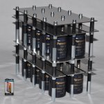
Yes, a prison. 80000uF good power for a channel. Lee capasitor nice selection (Panasonic). Have designed a soft start?
do you love music at high volume?
You build high-powered amplificator. What is the reason?
not yet begun to measure. I will build the circuit again.
then we'll do the measurement. I did greed.
I did greed. to be or to be. LTSpice I got yesterday. nice program. I was using proteus.
do you love music at high volume?
You build high-powered amplificator. What is the reason?
not yet begun to measure. I will build the circuit again.
then we'll do the measurement. I did greed.
I did greed. to be or to be
. LTSpice I got yesterday. nice program. I was using proteus.I bought a soft start circuit for this amp. It is different from most soft start circuits that are used in amplifiers.
The circuit is discussed here:
http://www.diyaudio.com/forums/pass...ter-solution-large-toroidal-transformers.html
I was looking for ready made soft start circuits because I didn't want to reinvent the wheel again. Nothing pleased me and I decided to try the Emeco thing.
I don't know yet whether it will work with the full 160.000 uF. At the moment I use only 40.000 uF and the light dims during power up of the amp.
I will test it this weekend.
I love music at high volume but where I live I can hear the neighbors fart. Thus I can't listen too loud.
I think the reason I built this amp is that I was looking for a challenge. I missed challenge at work. This might change.
Why do you build such a huge amplifier?
Why did you build four big amplifiers?
Why do you build the circuit again and not repair one of the four that don't work?
What do you mean with "greed"? I don't understand this.
What do you mean with "greed"? I don't understand this.
Well, ermm...cough...let me explain what greed is...greed means...you're loaded with money and 16 x 10000uf/100V is a fortune!
you're right about the soft start.
I am eagerly waiting for your test.
challenge? to whom?
"greed" mean ambitious.
I want to show my frends that I can do this.
I build this amp. for a long time but they didnt work.
I didnt repair becouse I didnt trust goods. becouse ıam tired of constantly reparing.
I am sorry Iwant to say there "I am greed" I want to achieve.
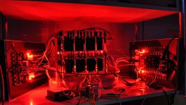
Tested the capacitor block today. I'm surprised the fuse didn't trip. It seems the soft start does a good job.
Plus the little buzz/hum is gone now. Obviously just 5cm of 2mm² ill conceived wire can mess up grounding completely.
Funny thing with the greed. In German "geizig" means greedy, and "ehrgeizig" means ambitious. Just a little difference but very different meaning.
Mustafa, I think repairing could be less expensive than to build everything from scratch again. But it's your choice.
Attachments
- Status
- This old topic is closed. If you want to reopen this topic, contact a moderator using the "Report Post" button.
- Home
- Amplifiers
- Solid State
- another one to build an AV800 / AV1000