Ok, the amp survived the square waves.
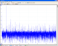
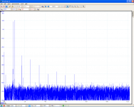
Let's see what the spectrum looks like. I have a lot of noise since my test setup was everything but clean (and the scope shows lots of noise anyway with shorted leads...) but spectrum still gives a hint how harmonics are distributed.
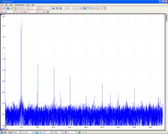
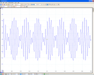
First one: 10kHz 32Vpp into 5R6 load.
Looks nice to me.
Dominant second harmonic, lower third, even lower fourth,... Interesting the 6th is higher than the 5th.
About your spectrum:
I am not Audio expert, but some considerations:
1) it looks like that the small problem with the 6th come from some external noise "beating" with some of your harmonics. Maybe an energy spare neon bulb or so on. They have nasty oscillators inside in the multi 10th of kHz range.
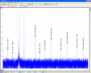
2) It might be intersting to see the spectrum generated by a 1kHz input, since most of the harmonics , if present, will be in the audible range.
About the PCB, if you do not mind, I will appreciate if you share it.
Cheers,
effebi
The place where I made the measurements was noisy indeed. To make it worse the input was connected with plain unshielded wire to the signal generator. I might have had some ground loops with all the equipment involved, the signal generator, the smps, the PC and who knows what else. A USB port isolator helped a lot getting rid of some very visible disturbance.
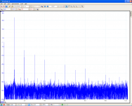
Sorry, I forgot the 1kHz spectrum.
I would share the pcb on request once it is completely finished, thoroughly abused and tested, listened to and found to sound okay.
It is everything but DIY friendly and someone who likes to build it had to use certain and even some very exotic parts like the input caps and the fancy output inductor. There's no allowance for replacements parts, neither footprint wise nor space wise. Assembly is a bit difficult but doable. Servicing the pcb would be a real pain. Once assembled it is near impossible to change certain parts.
If there are DIYers interested in this project they can contact me.
But first the design needs to be tested. I wouldn't give untested boards to anyone.
Attachments
To me the design looks friendly enough. At least all the components look like to have pins! With today's SMT cases that is not obvious any more.It is everything but DIY friendly and someone who likes to build it had to use certain and even some very exotic parts like the input caps and the fancy output inductor. There's no allowance for replacements parts, neither footprint wise nor space wise. Assembly is a bit difficult but doable. Servicing the pcb would be a real pain. Once assembled it is near impossible to change certain parts.
If there are DIYers interested in this project they can contact me.
But first the design needs to be tested. I wouldn't give untested boards to anyone.
I would have gone even more radical using more SMT components (capacitors, power resistors, and even MOS.I know there are trade-offs (think to the painful way to heat-sink SMT MOS). Anyway lt seems to be fair to mount and service in a modern way of thinking. Let's see what comes out, at the moment I only can say that you are on the right way.
The 1K spectrum shows something like 30dB 2nd harmonic rejection and close to 40 for 3rd right?
Not so bad..
bye effebi
Hi effebi
Agree, SMT is getting more and more extreme. Try hand soldering BGAs. We (company) don't use any despite mostly EMS manufacturing.
The only SMT components I used were 1206 and 2512 resistors.
First I intended to use SMT for some capacitors but soon dismissed the idea for two reasons: First is that one is not very flexible with SMT case sizes and what fits into them. Audio grade dielectrics like Mica and maybe COG ceramics might result in huge cases anyway so there's not much to gain space wise.
Second is that with SMT capacitors there's a risk that they might crack due to thermal or mechanical stress. Although I hand soldered countless 0805 caps and none failed I didn't feel comfortable with it. Reliability and flexibility was more important to me.
With the 1206 resistors I gained a lot of space but it was hard to find thin film ones and metal film ones were almost unobtainable for me. The SMT thin film ones were much more expensive than radial leaded metal film resistors.
Some transistors used in Audio are also available in SMT but afaik only a few and low power ones. Heatsinking SMT components is difficult as you pointed out.
Another advantage of THT components is that one is more flexible with pinout. For TO-92 just swap legs, easy in most cases. Not so easy with SOT23-3 or something.
"Anyway lt seems to be fair to mount and service in a modern way of thinking."
A very nice description.
The modern way of thinking is that I need to give my car away for replacing the light bulbs. They take out the engine in order to change the light bulbs and return the car with with a bill that reads 1500 Euro.
"Not so bad.."
Good to hear.
Do you think the scope and dummy load will get me any further?
I think about building a provisional wire harness to use the toroid, rectifier board and storage caps for further testing. This way I could test it with a real loudspeaker as well.
It might be a bit dangerous but "danger" and "safety" are very comparative terms anyway.
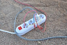
See what they do in Egypt. This is how the workers connected huge electric hammers to the mains. I've seen this many times. They seem to connect everything this way.
Thanks,
Lee
Agree, SMT is getting more and more extreme. Try hand soldering BGAs.
We (company) don't use any despite mostly EMS manufacturing. The only SMT components I used were 1206 and 2512 resistors.
First I intended to use SMT for some capacitors but soon dismissed the idea for two reasons: First is that one is not very flexible with SMT case sizes and what fits into them. Audio grade dielectrics like Mica and maybe COG ceramics might result in huge cases anyway so there's not much to gain space wise.
Second is that with SMT capacitors there's a risk that they might crack due to thermal or mechanical stress. Although I hand soldered countless 0805 caps and none failed I didn't feel comfortable with it. Reliability and flexibility was more important to me.
With the 1206 resistors I gained a lot of space but it was hard to find thin film ones and metal film ones were almost unobtainable for me. The SMT thin film ones were much more expensive than radial leaded metal film resistors.
Some transistors used in Audio are also available in SMT but afaik only a few and low power ones. Heatsinking SMT components is difficult as you pointed out.
Another advantage of THT components is that one is more flexible with pinout. For TO-92 just swap legs, easy in most cases. Not so easy with SOT23-3 or something.
"Anyway lt seems to be fair to mount and service in a modern way of thinking."
A very nice description.
The modern way of thinking is that I need to give my car away for replacing the light bulbs. They take out the engine in order to change the light bulbs and return the car with with a bill that reads 1500 Euro.
"Not so bad.."
Good to hear.
Do you think the scope and dummy load will get me any further?
I think about building a provisional wire harness to use the toroid, rectifier board and storage caps for further testing. This way I could test it with a real loudspeaker as well.
It might be a bit dangerous but "danger" and "safety" are very comparative terms anyway.
See what they do in Egypt. This is how the workers connected huge electric hammers to the mains. I've seen this many times. They seem to connect everything this way.
Thanks,
Lee
Attachments
Results
hi Lee,
Nice results sofar!
The square wave tests are looking good, overall stability looks fine.
How big is the feedback capacitor?
Did you check the thermal stability of the current idling current?
An intermodulation test would be very informative.
regards,
Piersma
hi Lee,
Nice results sofar!
The square wave tests are looking good, overall stability looks fine.
How big is the feedback capacitor?
Did you check the thermal stability of the current idling current?
An intermodulation test would be very informative.
regards,
Piersma
Hi Piersma
Great to read from you again.
The feedback cap is a 220uF bipolar one with 100nF foil in parallel.
I already planed bias vs. temperature measurements since I observed something interesting during initial test:
At room temperature (20°C) I set bias to 1A total and when I was finished the heat sink temperature was 50°C and bias 790mA. The module laid flat in front of me on the table so there wasn't any convection.
Today I further tested how bias changes with temperature:
8:00am I=1.13A Tamb=20°C Tsink=20°C DCoffset=21mV
8:05am I=0.99A Tamb=20°C Tsink=27°C DCoffset=15mV
8:15am I=1,00A Tamb=17°C Tsink=32°C DCoffset=14mV (let in some fresh air)
8:50am I=0.95A Tamb=19°C Tsink=41°C DCoffset=13mV
9:30am I=1.21A Tamb=00°C Tsink=22°C DCoffset=15mV (put it outside)
This confirmed my observation that the amp has a negative temperature coefficient. For a power amp this is not a too bad behavior, at least better than a positive one.
I assume bias has to do with the front end a lot. My theory is that little changes of the first LTP tail current result in drastic bias current changes. From the numbers I find that ambient temperature has more influence on bias current than heatsink temperature. I had not enough time to validate my theory. Easiest would be to touch the tail CCS and heat it with my fingers.
But this also makes me doubt whether my heat sink is big enough. This time it was vertical and had normal convection. With the real power supply it will have to dissipate twice as much heat.
How can I do an intermodulation test? What measurement equipment do I need and how to do the test?
Thanks,
Lee
I spent the afternoon with measurements.
Now I'm confused again.
First things first.
No.
Last things first.
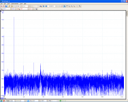
I found out that the Hameg 8030-4 adds a lot of harmonics and the PicoScope (3206) has a superior Wave Generator. I didn't expect this. The PicoScope generator has more third harmonics, the Hameg more second.
Attached spectrum of both loaded with probe only.
Now I'm confused again.
First things first.
No.
Last things first.
I found out that the Hameg 8030-4 adds a lot of harmonics and the PicoScope (3206) has a superior Wave Generator. I didn't expect this. The PicoScope generator has more third harmonics, the Hameg more second.
Attached spectrum of both loaded with probe only.
Attachments
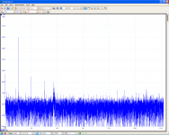
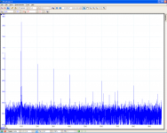
With the Picoscopes generator spectrum looks different.
I burnt my 5R6 load resistor and managed to find a 4R one with more power.
I can't set the level of the pico generator so results maybe aren't comparable anyway...
1k 36Vpp into 4R load
I burnt my 5R6 load resistor and managed to find a 4R one with more power.
I can't set the level of the pico generator so results maybe aren't comparable anyway...
1k 36Vpp into 4R load
Attachments
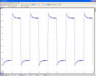
I forgot something:
Overdrive with sinewave. SMPS are 40V 5A. I can't remember whether they went into current limiting. Most likely they did so maybe the top of the waveform comes from that. But it looked that way all the time when I increased the input. I think this was when I blew my load resistor.
Forgot another thing:
Bandwidth.
3Hz...130kHz -3dB into 5R6 load at 20Vpp
3Hz...150kHz -3dB into 5R6 load at 30Vpp
Attachments
Last edited:
After looking at the spectrum plots for a while and thinking about what I see I came to the conclusion that this test didn't reveal much about the amplifiers behavior.
I made two big mistakes:
First was the sloppy input connection that picked up a lot of noise. After I fixed it everything looked much more reasonable.
Second was not to check the spectrum of my signal generator.
The spectrums of the amplifier's output actually reflect what harmonic content is present at the input from the signal generators. With the two different generators this became too obvious.
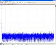
Intermodulations of harmonics are due to harmonic content at the input. I'd trust the f1-f2 and f2+f1 intermodulation artefacts since this are the base frequencies. For the 2k3 and 3k test the spikes at 700Hz and 5k6 are true, the rest is very generator dependant. In this spectrum the 2k3 was Hameg generated with lots of harmonics, the 3k was generated by the PicoScope with its typical harmonic footprint.
I'll do the wire harness then and just listen to the amp.
I made two big mistakes:
First was the sloppy input connection that picked up a lot of noise. After I fixed it everything looked much more reasonable.
Second was not to check the spectrum of my signal generator.
The spectrums of the amplifier's output actually reflect what harmonic content is present at the input from the signal generators. With the two different generators this became too obvious.
Intermodulations of harmonics are due to harmonic content at the input. I'd trust the f1-f2 and f2+f1 intermodulation artefacts since this are the base frequencies. For the 2k3 and 3k test the spikes at 700Hz and 5k6 are true, the rest is very generator dependant. In this spectrum the 2k3 was Hameg generated with lots of harmonics, the 3k was generated by the PicoScope with its typical harmonic footprint.
I'll do the wire harness then and just listen to the amp.
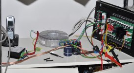
This is what my amp looks like at the moment.
Since I ran out of money it will look like this for a while now.
I will build the second channel and plan a nice housing in the future.
I already listened to it but can't tell you how it sounds.
I use a DIY active crossover because I don't like the bass of my full range speakers and have a 15" driver for everything below 100Hz. At the moment the Weld-a-Sym is used for the bass channel. Later it will be used for the fullrange speakers that run with my old DIY amp now.
Attachments
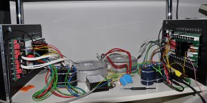
it's growing
Last weekend I finished the second channel.
Now I was set up for a listening test but it went wrong.
Used for the bass channel the amp worked fine and the only annoying thing was a massive thump at turn off which came from the DIY active crossover. The amp itself doesn't make any sound neither at startup nor shutdown. But the crossover does and this caused a catastrophe with the amp used for the fullrange speakers. It seems the crossover sends a blast of nasty noise out on the high pass channels when powered up and this fried one of my tweeters. The other theory is crackling contacts in provisional connectors. I'm glad the guys from the multi way speaker department helped me to find a replacement. I hope I can listen to music again soon. Next thing to add will be a delayed speaker insertion like my old DIY amp had who drove the fullranges before. I can't rely on other equipment to behave well during startup and shutdown.
Attachments
Lee , those amps look dynamite !!! among the best builds I have seen short of Anthony Holton himself !!!
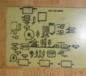
I designed a little retro AV like stage, "keep it simple" style (EX-below). I hope it works out as well as yours ... I still can't match your board quality. I am going to match this stage up with LatFET's (subamp).
Better watch what you hook to that amp , I'm sure any errata would be catastrophic at that power level !!
OS
Attachments
- Status
- This old topic is closed. If you want to reopen this topic, contact a moderator using the "Report Post" button.
- Home
- Amplifiers
- Solid State
- another one to build an AV800 / AV1000