Hi Jbau,
i know you were running these tests to develop a PS for a specific task but i was wondering if you would consider testing a couple of other configurations? One is the schematic i posted above - I would be willing to send you a lm329. The second configuration is the tracking preregulator, i can post a schematic later but i think 1 reg is acting as a current source for the other.
The reduced output impedance you measure when you run the adjust pin ground directly to the load is interesting. I would have expected to see an improvement in regulation not necessarily Zout. I need to think about this result some more. Nevertheless, i am pleased that i left room for this option on the PS boards i designed as it seems to really improve performance.
thanks again for posting your results.
jbau said:Salas, the graph of Jung's you posted is of ripple rejection, not output impedance.
Aren't they mutually related?
jbau said:So, to recap, where this has landed so far is, for ±15VDC:
LM317 - 80 / 880 with 10uF adjust cap (bypassed of course)
LM337 - 120 / 1k3 with 10uF adjust cap
1000-2200uF output cap, with as large a film bypass as you have room for (I like to put 10uF film across these)
Protection diodes as per data sheet.
Separate leads from each adjust circuit to the load ground.
Data taken into account. Thanks.
What about configuring a 317/337 as a CCS and directly feed one configured as a voltage regulator? A CCSed reg in other words? I think it could improve the performance.
I can't give this much time today, I have things to do outside. But I did look into the possible errors when measuring the LM337. And there was one mistake: using the same 10,000uF capacitor to block dc from the oscillator for both measurements and flipping the polarity. The time constant with 1000 ohm source is well over a minute, and it takes much longer than that for leakage currents to reverse and stabilize, 5-10 minutes. Until it stabilizes, these currents are flowing back to the oscillator and loading it's output, making it look like a lower impedance. And that's what was happening. I was working mostly on the LM317 and so the cap spent most of its time on the positive rail. The solution is to use separate 10kuF capacitors to isolate the oscillator and leave them connected to the regulator output all the time so they stay charged (maybe even ground the 1k ohm end to make sure), and only connect the oscillator output when needed.
Details, details. So many gotchas when measuring low impedances!
A correction to yesterday's post, I meant 10 mOhms not uOhms...
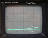
As to the unexpected linear Z of the LM337, I double-checked the analyser display scaling with .01 and .1 ohm resistors, no problems there. No errors in the 337 circuit. My hunch is that previous published graphs must have been done with very small output capacitors, 10uF are typical.
Here is a pic, linear impedance sweep to 20kHz, with 470uF and then adding 1000uF to it. (I'd have to take the fixture apart to remove the 470u, maybe some other time.) This is about what I would expect.
My conclusion is the LM337 responds very well to changes in output capacitance, better than its sibling 317.
Time to go buck some firewood. Which feels better in the hand, a spectrum analyser or a chainsaw?
Details, details. So many gotchas when measuring low impedances!
A correction to yesterday's post, I meant 10 mOhms not uOhms...
As to the unexpected linear Z of the LM337, I double-checked the analyser display scaling with .01 and .1 ohm resistors, no problems there. No errors in the 337 circuit. My hunch is that previous published graphs must have been done with very small output capacitors, 10uF are typical.
Here is a pic, linear impedance sweep to 20kHz, with 470uF and then adding 1000uF to it. (I'd have to take the fixture apart to remove the 470u, maybe some other time.) This is about what I would expect.
My conclusion is the LM337 responds very well to changes in output capacitance, better than its sibling 317.
Time to go buck some firewood. Which feels better in the hand, a spectrum analyser or a chainsaw?
Attachments
Hi Jbau,
very interesting. can you give some more specifics on the capacitors you are using (Type, ESR etc.)?
If your results with the 337 hold up i can't see much reason for using anything else on the negative rail. Zout flat and low across the audio band and you don't need to worry about external sensing.
very interesting. can you give some more specifics on the capacitors you are using (Type, ESR etc.)?
If your results with the 337 hold up i can't see much reason for using anything else on the negative rail. Zout flat and low across the audio band and you don't need to worry about external sensing.
hello.
i use the lm317/337 often with small chipamps like lm1876 and so .........
my idea is to squeeze the regulators between two big capacitor banks ( also a " c- reg. -c " filter),e. g. 10000uf at the input and - at the moment--2700uf at the output.
first i used 1000uf at the output,later on i changed to 2700uf , and i think that sounds a little bit better (more present,more fine detail in the high tone........).so i decided to go on with 4700uf..........but without damaging the regulators i hope.
could you test this kind of arrangement?
greetings............
Taking a break, time for a few replies.
I see strong correlation in the data sheets, but someone else knows this answer better than I.
Interesting idea. It would need more heatsink area so I wouldn't have room for it in my projects... please test it and report the results to us!
I have LM329's here, I'll give it a try - thanks.
I refurbish test equipment for a living so I have many parts chassis lying around to pull parts from. The 10000uF caps were all pulls, I had maybe a dozen. I didn't think ESR was important for this circumstance so I didn't check it. I thought leakage current was important. The best was a Philips 10000/35V cap, it was below 1uA which is excellent for that big a cap. Second best was about an unknown brand and just under 2uA. Some others were much higher.
I totally agree. If we can find a + regulator to match it I'm a happy camper.
Salas: ripple rejection... output impedance. Aren't they mutually related?
I see strong correlation in the data sheets, but someone else knows this answer better than I.
Salas: What about configuring a 317/337 as a CCS and directly feed one configured as a voltage regulator? A CCSed reg in other words? I think it could improve the performance.
Interesting idea. It would need more heatsink area so I wouldn't have room for it in my projects... please test it and report the results to us!
okapi: i was wondering if you would consider testing a couple of other configurations? One is the schematic i posted above - I would be willing to send you a lm329.
I have LM329's here, I'll give it a try - thanks.
okapi: can you give some more specifics on the capacitors you are using (Type, ESR etc.)?
I refurbish test equipment for a living so I have many parts chassis lying around to pull parts from. The 10000uF caps were all pulls, I had maybe a dozen. I didn't think ESR was important for this circumstance so I didn't check it. I thought leakage current was important. The best was a Philips 10000/35V cap, it was below 1uA which is excellent for that big a cap. Second best was about an unknown brand and just under 2uA. Some others were much higher.
okapi: If your results with the 337 hold up i can't see much reason for using anything else on the negative rail. Zout flat and low across the audio band and you don't need to worry about external sensing.
I totally agree. If we can find a + regulator to match it I'm a happy camper.
mjf: Of course the problem with that approach is that you're basically listening to the output cap impedance all across the audio band. Once I get my network analyser back up we can see the phase component of the impedance and that will tell us how the stored energy is delivered out of the big cap when needed. You probably already know the answer to that. If it was so good, we wouldn't be bypassing them with films. It would be ideal if we had a regulator with low, flat impedance without output filtering. But we're stuck somewhere in between these two extremes, and searching for a optimum balance. Also, your application is probably pulling more current than mine, which basically drives maybe a dozen opamps and some support circuitry.
mjf said:hello.
i use the lm317/337 often with small chipamps like lm1876 and so .........
my idea is to squeeze the regulators between two big capacitor banks ( also a " c- reg. -c " filter),e. g. 10000uf at the input and - at the moment--2700uf at the output.
first i used 1000uf at the output,later on i changed to 2700uf , and i think that sounds a little bit better (more present,more fine detail in the high tone........).so i decided to go on with 4700uf..........but without damaging the regulators i hope.
could you test this kind of arrangement?
greetings............
One caution you can take when using large output caps is to install the protection diode(s) as shown in the datasheets (if you haven't already). The diode that is 'across' the regulator,and reversed (cathode to input,anode to output) will protect the regulator from being reverse-biased from the potential voltage still on the large output cap on power-down.
IE,if the input cap discharges first,and there is still voltage on the output cap,it has somewhere to go (through the diode) instead of reverse-biasing the regulator,and potentially damaging it. Most regulators don't like the voltage on the output to go above the voltage on the input.
More accurate
Well the impedance gods were smiling on me yesterday, I was able to repair an HP 4276A LCZ meter that I had given up on a couple years ago. The previous owner had spent over a grand to replace the custom discrete IC's (made by Sony for HP) which he had blown by exceeding the DC volts limit of the input, but with no success. I just noticed yesterday that he had installed all 6 of the IC's backwards! Amazingly, they were not damaged by it. I owned a 4276A back in the early 90's and wrote a program for the HP 9845B to collect and plot the data. Today I'm glad I hung on to that computer!
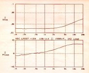
As I noted near the start, the spectrum analyser technique does not yield accurate numbers, but would show trends. The matter is compromised by the 10,000uF cap needed to isolate the DC from the oscillator output. At higher impedances it's not a problem. But at the milliohm impedances we're trying to measure, the capacitor's impedance rise with lower frequencies obscures the trends down there.
Here's the LM337 using the 4276A with 4-wire connection, looking more like we'd expect it to.
There is still some variability in the measurements due to equipment warmup, contact resistance, who knows what else. The same measurement made 1 hour later saw the baseline impedance value just under 10 mOhms, as opposed to the 15-ish mOhms of this sweep. But the shape of the curve was the same.
Updated LM317 to follow.
Well the impedance gods were smiling on me yesterday, I was able to repair an HP 4276A LCZ meter that I had given up on a couple years ago. The previous owner had spent over a grand to replace the custom discrete IC's (made by Sony for HP) which he had blown by exceeding the DC volts limit of the input, but with no success. I just noticed yesterday that he had installed all 6 of the IC's backwards! Amazingly, they were not damaged by it. I owned a 4276A back in the early 90's and wrote a program for the HP 9845B to collect and plot the data. Today I'm glad I hung on to that computer!
As I noted near the start, the spectrum analyser technique does not yield accurate numbers, but would show trends. The matter is compromised by the 10,000uF cap needed to isolate the DC from the oscillator output. At higher impedances it's not a problem. But at the milliohm impedances we're trying to measure, the capacitor's impedance rise with lower frequencies obscures the trends down there.
Here's the LM337 using the 4276A with 4-wire connection, looking more like we'd expect it to.
There is still some variability in the measurements due to equipment warmup, contact resistance, who knows what else. The same measurement made 1 hour later saw the baseline impedance value just under 10 mOhms, as opposed to the 15-ish mOhms of this sweep. But the shape of the curve was the same.
Updated LM317 to follow.
Attachments
")
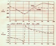
Busy week, sorry for the delay. Here are two measurements of the Nat Semi LM317 with the HP 4276A, same setup as before, looking just as stinky as it did with the spec an. One sweep with 470uF on the output, another with 2,200uF. This again confirms the sweet spot (that's a generous term) for the output cap is somewhere in the 1500-2200uF range. Note the 360º impedance phase cycling with resonance at 600Hz or so. If a lesser bump at 2.5kHz is extremely audible, this dip can't be a good thing, right in the heart of the midrange.
To see if this was a brand-specific issue, I tested a 317 from TI and another NSC from a different date code and they all looked appreciably the same. I also tested an instrument that I had been repairing this week which used LM317/337, and same results.
So it looks like the 317 is a lower bandwidth device than the 337. Any ideas on how to address this?
Attachments
is that 360 degree phase shift when the reg become inductive present with the spec sheet recommended cap values?
the frequency of resonance is predictable: 1/(2pi rootLC) - the lm317 inductance with the load current above 0.1 A is about 1 microH.
i am inclined to think the resonance you observed is related to cap esr. try putting a small value resistor in series with the cap - this will also increase output impedance but perhaps you'll be able to find a reasonable compromise. 180 degree phase shift is definitely something to be avoided as what what negative feedback is now positive feedback.
an alternative approach might be to increase your adjust bypass cap to 1000 uF or more, your load current to 0.5 A or more and use a smaller output cap. According to Erroll Dietz this should also give low output impedance.
could you also comment on how the HP 4276A measures phase?
okapi
is that 360 degree phase shift when the reg become inductive present with the spec sheet recommended cap values?
Yes, you can see it in my previous measurements too.
i am inclined to think the resonance you observed is related to cap esr. try putting a small value resistor in series with the cap
I played around with this last week and it was not significant in the audio band. But I'll try it again today.
an alternative approach might be to increase your adjust bypass cap to 1000 uF or more
I have already shown, this will lower noise but make the resonance worse.
your load current to 0.5 A or more
I am not a fan of dumping 1/2 amp of power supply noise directly onto the same "ground" that I am using to reference gain and active filtering to.
and use a smaller output cap.
As you can see, above the resonance, the output cap is the dominant factor.
According to Erroll Dietz this should also give low output impedance.
My measurements don't agree.
could you also comment on how the HP 4276A measures phase?
All of the active impedance bridges are pretty similar in principle. HP writes great manuals - you can download the 4276A manual and read the operation theory section:
http://www.home.agilent.com/agilent...=805925&lc=eng&cc=US&nfr=-536900197.536897568
I woke up thinking, the 317 curve looks just like an opamp that has run out of gain bandwidth. I'm going to try some things today with that in mind.
The Agilent Impedance Measurement Handbook is also excellent. That's where I found the formulas for open/short/load compensation years ago.
http://cp.literature.agilent.com/litweb/pdf/5950-3000.pdf
http://cp.literature.agilent.com/litweb/pdf/5950-3000.pdf
The saga continues.
Okapi: I checked again your cap resonance theory and this is not an ESR-related resonance. Adding R up to 27 ohms made no difference.
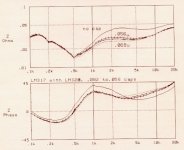
I put together the LM317 version of the circuit shown in your post #16, reversing the LM329 of course. For +15V output R2 = 750 ohms. It worked fine. I didn't measure the noise because in my mind if the impedance is screwed up I don't care how quiet it is.
The impedance sweep is below, compare it to the normal scheme in post #55. It's a step in the right direction, the resonance is damped so the phase doesn't cycle through and the impedance bump around 6kHz is lower too. (When comparing, note the different graph scales, my program auto-scales to the first measurement in each plot series...)
I noticed there was no cap to shunt the noise of the LM329 so I played around with that (across R2). The plot starts with no cap, then 100n, 150n, 220n, and 470nF. It was obvious where this story was going so I stopped. Just as we saw with the resistor-only version, the LM317 does not like to see a large capacitance on the adjust pin (the LM329 impedance at audio freq's is around 1 ohm). It resonates across the 750 Ohm R2 after 220nF.
Okapi: I checked again your cap resonance theory and this is not an ESR-related resonance. Adding R up to 27 ohms made no difference.
I put together the LM317 version of the circuit shown in your post #16, reversing the LM329 of course. For +15V output R2 = 750 ohms. It worked fine. I didn't measure the noise because in my mind if the impedance is screwed up I don't care how quiet it is.
The impedance sweep is below, compare it to the normal scheme in post #55. It's a step in the right direction, the resonance is damped so the phase doesn't cycle through and the impedance bump around 6kHz is lower too. (When comparing, note the different graph scales, my program auto-scales to the first measurement in each plot series...)
I noticed there was no cap to shunt the noise of the LM329 so I played around with that (across R2). The plot starts with no cap, then 100n, 150n, 220n, and 470nF. It was obvious where this story was going so I stopped. Just as we saw with the resistor-only version, the LM317 does not like to see a large capacitance on the adjust pin (the LM329 impedance at audio freq's is around 1 ohm). It resonates across the 750 Ohm R2 after 220nF.
Attachments
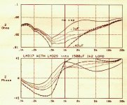
After seeing that, I decided to try lower-value caps. The plot below is with 56n, 68n, and 82nF. It's hard to tell, but the 82nF trace is the middle of the three lower traces. So the impedance went down until 68nF then went back up again at 82nF and then starts going down again as seen in the previous post. 68nF | 750 Ohms = 3.1kHz. Which is really close to Steve's Sandler's suggested RC value for optimum LM317 phase margin:
Part 1: http://www.aeng.com/pdf/regulator.pdf
Part 2: http://www.ema-eda.com/products/other/articles/Regulator2.pdf
Notice that the 68nF curve is about the same as the 100nF curve except that it doesn't affect the resonance. So the 68nF across R2 as the best.
Part 1: http://www.aeng.com/pdf/regulator.pdf
Part 2: http://www.ema-eda.com/products/other/articles/Regulator2.pdf
Notice that the 68nF curve is about the same as the 100nF curve except that it doesn't affect the resonance. So the 68nF across R2 as the best.
Attachments
- Status
- This old topic is closed. If you want to reopen this topic, contact a moderator using the "Report Post" button.
- Home
- Amplifiers
- Power Supplies
- Another look at the LM317 and LM337 regulators