Nice jbau, keep it coming!
http://www.acoustica.org.uk/t/3pin_reg_notes1.html
http://www.acoustica.org.uk/t/naim/317_ RC_filter.html
I'd like to see this investigated within this series... here are my few thoughts on the matter:You may also want to consider the use of a external voltage reference, as i have done, to get noise even lower.
http://www.acoustica.org.uk/t/3pin_reg_notes1.html
http://www.acoustica.org.uk/t/naim/317_ RC_filter.html
okapi: Yes, it might be, if noise was my main concern. But it isn't. The theory I'm chasing here is that it is a major drawback of split supplies that the quiescent state impedance characteristics of the two rails are not identical. I'm not sure if I've ever heard a piece of audio gear that has impedance-balanced rails. I'm not even sure what to call it. ")
If it turns out that it IS an important parameter, then all the listening tests that I (and everyone else) have conducted without it have been on a flawed platform and need to be redone. Wouldn't that be ducky.
martin: Thanks, yes I've seen your site and was intrigued. Couldn't follow it all, I must admit but I'll have another look.
Well I shorted out a 317 by accident and had to replace it so I got to look at another Nat Semi 317. At least they are pretty consistent...
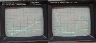
The bad news is, I could find no combination of set resistors, adjust cap, or load cap that makes the 317 impedance anywhere near as linear as the 337. I changed the measurement setup a bit to get better resolution at the low impedances, so these displays are 0 to 0.1 ohms full scale now. See the left pic. Lower values in the set resistors do help the 317, the lowest I tried was 80/900 || 10uF. Increasing the idle load current also helps it, shown with 25mA. The 337 did not change much with 25mA load current so I left it as it was.
Also see the right pic which shows the same measurement on a log frequency scale, to 40kHz. The 337 Z curve is very nice, below 0.02 Ohms throught the audio band. The Nat Semi 317 peaks at 0.055 ohms at about 7kHz, higher than the old Motorola part but still pretty nonlinear.
I have one major problem with adding more circuitry to improve the 317. On two of the units this would be going into, I have to modify the traces and graft parts onto the bottom of the pc board, and there isn't much real estate to work with.
I'd like to find a positive regulator that was a better match for the good LM337. The 317 impresses me as not that great a unit for audio.
I don't know why the sweep of the 337 didn't show the tracking filter tracing down from DC. Maybe the big lytic has different leakage in one direction? Also note, there is some impedance change caused by thermal drift, the 337's baseline impedance changed by almost half in the ten or so minutes between these photos as the system continued to warm up.
I have a couple more things to try tomorrow before I punt on the 317 and look for another + regulator, so I'm open to suggestions.
Attachments
The impedance curve you obtain for the LM337 is quite surprising. That device has a gain setting that falls at 6dB per octave starting at about 100hz. I just don't understand how it is possible to get a flat response up to 20khz. I have used a similar negative regulator (LT1033) and see an output impedance profile that matched what you see with the 317 not the 337. Is it possible that there is an error in how the device is being tested?
Salas said:No, cant be wrong. Jung has tested it with same bad findings.
I've got: Regulators for high performance audio by Walt Jung (part 2) in front of me. Figures 18a and 18b show output impedance rising around 10khz for 317 and 2khz for the 337.
i have never seen a flat output impedance curve up to 20khz from a 337, as jbau is reporting.
EDIT,i had the incorrect fig#s
okapi: There is no error, the only change for measurement of + and - output is the polarity of the output cap. I would be cautious with your results using a broadband voltmeter to measure the signal levels at issue here. Resolving a signal at or below -120dBV in the presence of noise with a broadband meter is questionable.
As to the 337 results, I think we'll see as things progress that there is considerable variation from unit to unit and from different manufacturers. It's quite possible that we should be selecting matched pairs of regulators. Think about it, a single-supply system doesn't have this problem
Sy: I agree with you entirely, but noone is advocating 6 ohms across the board. I want it to be as low as possible and as flat as possible. But I consider say 80Hz to say 5kHz to be sacred territory in audio. That's where the real musical content is. And resonances in that band are to be avoided if possible.
I've already proven to myself that an impedance bump up to .1 ohms from a .03 ohm floor at 2.5kHz in the positive regulator only is VERY audible and quite objectionable.
jbau said:okapi: There is no error, the only change for measurement of + and - output is the polarity of the output cap. I would be cautious with your results using a broadband voltmeter to measure the signal levels at issue here. Resolving a signal at or below -120dBV in the presence of noise with a broadband meter is questionable.
.
Noise can definitely obscure the measurement and you have to tweak the set up to be able to resolve very low output impedances. Nevertheless, the method can easily resolve the rising impedance slope that i have seen on LT1033 regulators and Jung has reported in LM337 regs.
I was unable to improve upon yesterday's findings with the LM317, except to say that the protection diodes do help a little bit too. Larger output caps do help for both units, but there is a point of diminishing improvement somewhere in the 1000-2000uF range. So yesterday's findings are the end of the line for these units with standard compensation techniques.
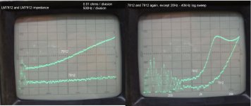
While I'm set up for measuring this, I thought it would be useful to look at the rails of one of the units I will be modding. It has 7812 and 7912 regulators, static load is 7 dual opamps plus four 5-volt regulators draw from it as well (3 from the +, one from the -). So load idle load current is certainly above the 25mA. I can't see the mfr of these IC's, they are buried behind the filter caps.
See the pics, same setup as yesterday, with 0.01 ohms per division. First pic DC-5kHz, followed by the 20Hz-40kHz log sweep. The 7912 is the worse performer in this duo. The 7812 is respectably good up to 4-5 kHz before it rises. The 7912 is higher overall and resonates at about 7kHz. Notice also that both units get better as they warm up, the right pic was made 10 minutes after the first and the baseline impedance had fallen quite a bit. (Now we have a measurement that shows why things sound better when they warm up.)
The LM7812 and LM337 results are the most similar of all those encountered. So to test my theory, I am going to optimize a pair using LM337 for the negative and LM7815 for the positive, install in the Sony dac, sweep again to make sure the curves match, and do some listening. Should be interesting.
Attachments
walt jung articles can be found here:
http://www.waltjung.org/Regs.html
the 95' articles are the ones i am referencing.
http://www.waltjung.org/Regs.html
the 95' articles are the ones i am referencing.
okapi: yes, resolving the rise is possible, but not the lower details. I have several 6.5 digit meters here from HP, Keithley, and others and they can't do it accurately. I also tried doing it with an HP 35660A FFT and lots of averaging and it doesn't do it well either. The selectivity of a sweeping bandpass filter is unmatched for this sort of work.
here is another reference showing the output impedance rise at 1khz for a 337.
http://www.national.com/ds/LM/LM137.pdf
To measure very low output impedances you need to input a larger current so that the noise does not obscure the measurement. A good meter is required but it is not the only requirement for this technique.
http://www.national.com/ds/LM/LM137.pdf
To measure very low output impedances you need to input a larger current so that the noise does not obscure the measurement. A good meter is required but it is not the only requirement for this technique.
okapi, I don't want to argue. I trust my measurements more than I trust data sheets any day. And I have considerable experience with impedance measurements for many years. 15 years ago I wrote programs that will perform the open/short/reference compensation used by HP's best Z analysers, and allow one to do just as accurate Z measurements (mag and phase) with a network analyser, a current probe, and a simple fixture. In fact, HP's old 3570A/3330B system is superb for this. You can pick these up for peanuts these days. And HP's old 4800A is excellent but only down to 0.1 ohms and only for passive components. I use mine daily.
Gotta go, the regulators are calling...
Gotta go, the regulators are calling...
Hi Jbau,
i don't want to argue either, I am really just trying to understand one result you posted. I am really quite pleased that you are posting measurements as they are relatively rare on diyaudio and i don't want to behave in a way that discourages you from sharing your experimental results here. I want to learn from them.
in that light, can you explain why the 337 has a flat frequency response up to 20khz and the 317 does not?
thanks in advance for your thoughts.
okapi: Thank you, I think we're on the same page. I too am trying to learn from these measurements, and I am especially interested when a measurement correlates strongly with what I hear it doing. Used wisely, there's no better teacher than a spectrum/network analyser.
I can't explain the LM337 results, any more than I can explain the 7812. We'll see if the 7815s I have here are similar. I do know that manufacturing tolerances cannot be discounted, for any device.
Like I said, I can see how this may turn out to be a situation where we have to measure and select matched pairs of regulators. And then, after they are installed and warmed up in each piece of gear, tweak the idle current of the poorer one to match the impedance of the other. And if we know in advance that the curves are relatively flat, this can be done at only one frequency with some confidence of the outcome.
Salas said:No, cant be wrong. Jung has tested it with same bad findings.
okapi said:
I've got: Regulators for high performance audio by Walt Jung (part 2) in front of me. Figures 18a and 18b show output impedance rising around 10khz for 317 and 2khz for the 337.
i have never seen a flat output impedance curve up to 20khz from a 337, as jbau is reporting.
EDIT,i had the incorrect fig#s
Sorry, I mixed jbau 317 rising plot. Yes you are right. Mysterious. Here it is from Jung as CCS.
Attachments
Salas, the graph of Jung's you posted is of ripple rejection, not output impedance. That said, I agree, the LM337 high-freq measurement result doesn't make sense. That the filter shape didn't trace down from DC is suspect too. I'll have to look into it.
I checked out some 7815's from various manufacturers. They all stink, even when loaded down. There's no reason to post any photos, they are ugly. The ones from TI and Fairchild were particularly bad. The Nat Semi LM340-15 was the best of the lot but still not pretty.
The 7812s were better especially one from Mitsubishi which looked pretty good, like the one in the measurement posted earlier.
I also tested LM317s from Motorola and Fairchild. Very bad. I'd like to see what the JRC's look like. Stick with the Nat Semis for now.
I installed the reg circuits in the Sony and swept the them, the 5kHz sweeps looked just like the last measurements. Warmed it up and listened. The lows mids were impressive, the "glare" was gone, but the bass seemed weak. Then I remembered that I forgot to use the separate leads for the adjust to the load. Ooops. Hooked them up, re-did the Z sweeps, and was surprised to see that the curves were actually pulled below the baseline. So below 10 microohms this technique isn't good. Interesting that moving the adjust terminal reference out to the load actually decreased the output impedance. I changed the scaling enough so I could see the traces and they did overlap nicely below 4kHz, that's going to have to be good enough for now.
Have been listening for the last couple hours and it is very impressive indeed. The definition and detail in the bass and midrange is really superb, with a much better defined soundstage. The midrange glare reported earlier is totally absent.
There is something zippy up in the 8-10kHz range, but this is clearly a huge step in the right direction. There are other things that may be causing this, one of which I'll be investigating shortly.
So, I am unable to actually test my "impedance balance" theory for the moment, until I get the measurement situation sorted out.
So, to recap, where this has landed so far is, for ±15VDC:
LM317 - 80 / 880 with 10uF adjust cap (bypassed of course)
LM337 - 120 / 1k3 with 10uF adjust cap
1000-2200uF output cap, with as large a film bypass as you have room for (I like to put 10uF film across these)
Protection diodes as per data sheet.
Separate leads from each adjust circuit to the load ground.
- Status
- This old topic is closed. If you want to reopen this topic, contact a moderator using the "Report Post" button.
- Home
- Amplifiers
- Power Supplies
- Another look at the LM317 and LM337 regulators