JR Audio "Impossible" tonearm
Finally another commercial tonearm joined in the genre of pivoting tangential trackers. JR Audio from Poland named it the "Impossible". It looks similar in concept to the Thales Easy tonearm that pivots the headshell but the pivot point is not aligned with the stylus point. The method of guiding rod is of course from the Garrard Zero 100 lineage.

----------------------------------
Another look at the Thales EASY:

Finally another commercial tonearm joined in the genre of pivoting tangential trackers. JR Audio from Poland named it the "Impossible". It looks similar in concept to the Thales Easy tonearm that pivots the headshell but the pivot point is not aligned with the stylus point. The method of guiding rod is of course from the Garrard Zero 100 lineage.
An externally hosted image should be here but it was not working when we last tested it.
An externally hosted image should be here but it was not working when we last tested it.
An externally hosted image should be here but it was not working when we last tested it.
An externally hosted image should be here but it was not working when we last tested it.
An externally hosted image should be here but it was not working when we last tested it.
An externally hosted image should be here but it was not working when we last tested it.
An externally hosted image should be here but it was not working when we last tested it.
----------------------------------
Another look at the Thales EASY:
An externally hosted image should be here but it was not working when we last tested it.
Hi Doug: My own investigations (which may or may not be free of errors or lack of insights) suggest that when using a Birch-like system (aligning to a single point), a long guide arm_short swing arm geometry results in less tracking error.
When experimenting with fairly small-diameter Thales circles, swing arm lengths of 1/3 the Thales circle diameter or less generally showed less angular errors, but since I failed to take detailed notes of the deviations, I can't quote the numbers. Later I did plot charts of the angular deviations, but for much larger-diameter Thales circles (the turntable that I am using for these experiments has a platter diameter of 374mm). These configurations (for example, 468mm Thales circle, 156mm swing arm) showed a maximum tracking error of under 0.007 degrees.
I plan to revisit smaller-diameter Thales circles in the near future, and hopefully I will have the presence of mind to record the data.
kind regards, jonathan
The resonance results bothered me so I built a lighter aluminum headhshell which brought the Effective Mass down to about 3 gr and both resonances down to about 11 Hz and I think I can hear a difference. If clear detail and sharp soundstage are the hallmarks of an LT, this arm definitely is one.
DD,
I really like the angular appearance of that Polish arm. I hope it sounds as good as it looks.
Jonathon,
I'm very interested in your findings. Just to be sure: Is the "guide arm" the one that pivots at point P and supports the "swing arm," which carries the headshell? My Thales diameter is 320 mm, the swing arm is 218 mm, and the guide arm is 40 mm. If I understand you right, for 320 mm the swing arm should be about 107 mm. Man, that's short and brings up questions about the actual construction.
Just to be sure: Is the "guide arm" the one that pivots at point P and supports the "swing arm," which carries the headshell? My Thales diameter is 320 mm, the swing arm is 218 mm, and the guide arm is 40 mm.
In case Jonathan might have different nomenclatures, let's revisit the Birch drawing I posted multiple times before so everyone is on the same page. Below is a tentative system.
"Guide arm" = P to D (or pivot base)
"Swing arm" = C to D (or Main arm that holds the cartridge)
Thales triangle = A + B + C
An externally hosted image should be here but it was not working when we last tested it.
Doug, Ralph: Yes, we are using the same terminology. P to D is called guide arm, and C to D is called swing arm or main arm. A to B is the diameter of the Thales circle, and A + B + C is the Thales triangle.
I need to take another trip through my previous drawings to refresh my memory as to the exact procedures that were used, but the final group of drawings (468mm Thales circle, 156mm swing arm) plots the angular deviation across the LP at 0.25-degree intervals.
I am in the process of making new drawings (partly to reconfirm the design procedure), initially with a 345mm Thales circle (345~365mm is the approximate length of a 12-inch tonearm). The swing arm length is provisionally 115mm, but I could make drawings for different swing arm lengths to see how the angular deviations work out. I have unfilled drawings for Thales circle diameters of 310mm and 330mm, so I suppose that I could work through Doug's geometry (320mm diameter Thales circle, 218mm swing arm, 40mm guide arm) to find the configuration with the lowest angular deviation.
The starting variable is the Thales circle diameter, but a second variable is the swing-arm length ratio (of the Thales circle), and a third variable is in where the tonearm designer decides to place the 3 null points (where the angle of cartridge stylus to platter spindle is truly 90 degrees). Change the LP radii that the null points are assigned to, and the position of P will shift. IOW, there are quite a few permutations that should be considered and tried for any given Thales circle diameter.
I very much agree with Doug about the need for an appropriate construction. This type of arm places at least two bearing sets in series (one at P, one at D), with additional mechanisms needed to accomplish the C-to-B guidance. Since each bearing may introduce slop, noise, and friction, the performance of this type of tonearm will be limited by mechanical construction as well as geometry.
kind regards, jonathan
The starting variable is the Thales circle diameter, but a second variable is the swing-arm length ratio (of the Thales circle), and a third variable is in where the tonearm designer decides to place the 3 null points (where the angle of cartridge stylus to platter spindle is truly 90 degrees).
How can the respective angle not be 90 degree in a Thales circle?
Hi alighiszem: When designing and using physical parts, the guide arm must have a fixed length, and the swing arm must also have a fixed length (unless a length-adjusting mechanism is implemented, which would introduce additional bearing errors).
In my investigations so far, it looks like these two fixed lengths (in conjunction with the guidance to a single point B) cause stylus positions C to wander both inside and outside of the Thales circle as the tonearm traverses the LP (referring to Directdriver's post #824). IOW, the Birch concept seems to give three null points where stylus positions C reside exactly on the Thales circle, and depending on how the tonearm designer chooses the null points, the maximum tracking error will change, and how the tracking error is distributed across the LP will also change.
The exception is when bearing point B is at the Thales circle midpoint and bearing point D coincides with stylus positions C. This solution, shown earlier in this thread by Frank Schroder, and I believe the solution used by Micha Huber for the first Thales tonearm, will allow the stylus to always stay on the Thales circle and thereby eliminate tracking error. However, this solution places the bearings right above the cartridge stylus, so the mechanical building aspect would be quite a challenge.
Note that the above thoughts are based on my limited geometrical investigations, and there is every chance that I am overlooking something blindingly obvious. Corrections and thoughts are welcome") .
.
kind regards, jonathan carr
In my investigations so far, it looks like these two fixed lengths (in conjunction with the guidance to a single point B) cause stylus positions C to wander both inside and outside of the Thales circle as the tonearm traverses the LP (referring to Directdriver's post #824). IOW, the Birch concept seems to give three null points where stylus positions C reside exactly on the Thales circle, and depending on how the tonearm designer chooses the null points, the maximum tracking error will change, and how the tracking error is distributed across the LP will also change.
The exception is when bearing point B is at the Thales circle midpoint and bearing point D coincides with stylus positions C. This solution, shown earlier in this thread by Frank Schroder, and I believe the solution used by Micha Huber for the first Thales tonearm, will allow the stylus to always stay on the Thales circle and thereby eliminate tracking error. However, this solution places the bearings right above the cartridge stylus, so the mechanical building aspect would be quite a challenge.
Note that the above thoughts are based on my limited geometrical investigations, and there is every chance that I am overlooking something blindingly obvious. Corrections and thoughts are welcome
.kind regards, jonathan carr
Regardless how one designs the links using the Birch concept, whether long main-arm/short guide-arm or short main-arm/long guide arm, the design will always involve challenges of, as Jonathan pointed out, geometric precision, friction, noise, mass distribution, and rigidity, etc... One thing I want to add is that without any force compensation, all the Birch or Huber approaches, will exhibit some skating force. And from my understanding is that the closer point P is to point B, the less skating force but at the same time more angle deviation, I believe. So, future arm designer/builder has to keep that in mind in decision making.
Picture this: an imaginary "perfect" tonearm, it would be a single straight piece of wand that magically extends its length from C to B as it pivots closer to spindle A while maintaining the same mass in the process. Voila, a constantly shifting Thales triangle! Alas, such magic wand does not exist so we have to cheat it. This is where the creativity comes in...
I have thought of using the Dynavector split-plane design combined with linear bearing or rollers that rides on a cantilevered bridge of B to D but this bridge is longer than the main arm, which doesn't have to be so long and heavy that allows easier linear bearing or roller movement. This way the "guide arm" does not have to be the support of the entire arm as B is now the center of all the mass. Sorry, I'm just thinking out loud here and it might seem like a belabored way to lessen skating force so I'm not so sure. This is fun and headache inducing at the same time. Aren't we masochists?
An externally hosted image should be here but it was not working when we last tested it.
An externally hosted image should be here but it was not working when we last tested it.
Hi all: Here are some numbers that should illustrate the trends that I have been talking about.
First triplet of number lists involves a Thales circle diameter of 345mm, and a swingarm length of 115mm (one-third the Thales circle diameter). The variable is in where the three null points have been set. As you will see, shifting the null points alters how the tracking error is distributed across the LP, and the maximum tracking error, but it also affects the optimal guidearm length (and the location of pivot position P, but let's leave that for another time).
If you refer to the drawing that directdriver posted, the B-C-C "triangle" has been chopped up into 0.25-degree segments for analysis. A finer grid than 0.25 degrees will give more accurate results, but would involve more work. For the time being, I chose to use a moderate grid that is fine enough to establish the general trends, but isn't too taxing of a workload.
In each list, the lines marked with # are the null points that I chose. The lines marked with * are the tracking error peaks that resulted, with the caveat that a finer grid than 0.25 degrees may show slightly different results. Line 64 is the innermost LP groove, line 01 is the outermost LP groove, but the 0.25-degree grid starts with line 64, making the difference between lines 01 and 02 less than 0.25 degrees (considerably less, in this particular case).
After the line number (01-64), the first number in each line is the distance between the measurement point and the platter spindle (strictly speaking, this isn't the LP radius, since it includes the distances by which the momentary stylus position C oversteps or understeps the circumference of the Thales circle).
The second number in each line is the angle between the BC (line between pivot and stylus) and CA (line between stylus and platter spindle).
Any difference between the second number in each line and 90 degrees is the tracking error, which is the third number in each line. I have only added the third number for the tracking error peaks - so that they stand out on their own.
List 1: Thales circle diameter 345mm, guidearm length 115mm, swingarm length 97.45159mm
*01. 146.6mm 90.01405 degrees +0.01405
02. 146.31647mm 90.01324 degrees
03. 144.95182mm 90.00949 degrees
04. 143.58441mm 90.00605 degrees
05. 142.21426mm 90.00288 degrees
#06. 140.84141mm 90.00000 degrees
07. 139.46588mm 89.99738 degrees
08. 138.0877mm 89.99502 degrees
09. 136.70688mm 89.99291 degrees
10. 135.32346mm 89.99103 degrees
11. 133.93747mm 89.98939 degrees
12. 132.54892mm 89.98797 degrees
13. 131.15786mm 89.98676 degrees
14. 129.76429mm 89.98575 degrees
15. 128.36826mm 89.98494 degrees
16. 126.96978mm 89.98432 degrees
17. 125.56888mm 89.98388 degrees
18. 124.16559mm 89.98360 degrees
*19. 122.75994mm 89.98349 degrees -0.01651
20. 121.35195mm 89.98354 degrees
21. 119.94165mm 89.98373 degrees
22. 118.52907mm 89.98406 degrees
23. 117.11423mm 89.98452 degrees
24. 115.69716mm 89.98511 degrees
25. 114.27788mm 89.98581 degrees
26. 112.85644mm 89.98661 degrees
27. 111.43284mm 89.98751 degrees
28. 110.00712mm 89.98850 degrees
29. 108.57931mm 89.98957 degrees
30. 107.14943mm 89.99072 degrees
31. 105.71751mm 89.99193 degrees
32. 104.28358mm 89.99319 degrees
33. 102.84766mm 89.99450 degrees
34. 101.40978mm 89.99584 degrees
35. 99.96998mm 89.99721 degrees
36. 98.52827mm 89.99860 degrees
#37. 97.08468mm 90.00000 degrees
38. 95.63925mm 90.00139 degrees
39. 94.19199mm 90.00277 degrees
40. 92.74295mm 90.00413 degrees
41. 91.29213mm 90.00545 degrees
42. 89.83958mm 90.00672 degrees
43. 88.38532mm 90.00792 degrees
44. 86.92938mm 90.00906 degrees
45. 85.47178mm 90.01011 degrees
46. 84.01255mm 90.01105 degrees
47. 82.55172mm 90.01188 degrees
48. 81.08932mm 90.01258 degrees
49. 79.62538mm 90.01312 degrees
50. 78.15993mm 90.01350 degrees
*51. 76.69298mm 90.01369 degrees +0.01369
52. 75.22457mm 90.01367 degrees
53. 73.75473mm 90.01342 degrees
54. 72.28349mm 90.01292 degrees
55. 70.81087mm 90.01215 degrees
56. 69.33691mm 90.01107 degrees
57. 67.86162mm 90.00965 degrees
58. 66.38504mm 90.00787 degrees
59. 64.9072mm 90.00570 degrees
60. 63.42812mm 90.00309 degrees
#61. 61.94783mm 90.00000 degrees
62. 60.46637mm 89.99639 degrees
63. 58.98375mm 89.99222 degrees
*64. 57.5mm 89.98743 degrees -0.01257
List 2: Thales circle diameter 345mm, guidearm length 115mm, swingarm length 97.55125mm
01. 146.6mm 90.01332 degrees +0.01332
02. 146.31647mm 90.01254 degrees
03. 144.95182mm 90.00898 degrees
04. 143.58441mm 90.00571 degrees
05. 142.21426mm 90.00272 degrees
#06. 140.84141mm 90.00000 degrees
07. 139.46588mm 89.99754 degrees
08. 138.0877mm 89.99534 degrees
09. 136.70688mm 89.99338 degrees
10. 135.32346mm 89.99166 degrees
11. 133.93747mm 89.99016 degrees
12. 132.54892mm 89.98887 degrees
13. 131.15786mm 89.98780 degrees
14. 129.76429mm 89.98692 degrees
15. 128.36825mm 89.98624 degrees
16. 126.96977mm 89.98574 degrees
17. 125.56888mm 89.98541 degrees
*18. 124.16559mm 89.98525 degrees -0.01475
*19. 122.75994mm 89.98525 degrees -0.01475
20. 121.35195mm 89.98540 degrees
21. 119.94165mm 89.98569 degrees
22. 118.52907mm 89.98611 degrees
23. 117.11423mm 89.98666 degrees
24. 115.69716mm 89.98733 degrees
25. 114.27788mm 89.98811 degrees
26. 112.85644mm 89.98899 degrees
27. 111.43284mm 89.98995 degrees
28. 110.00712mm 89.99101 degrees
29. 108.57931mm 89.99214 degrees
30. 107.14943mm 89.99333 degrees
31. 105.71751mm 89.99459 degrees
32. 104.28358mm 89.99589 degrees
33. 102.84766mm 89.99723 degrees
34. 101.40978mm 89.99861 degrees
#35. 99.96998mm 90.00000 degrees
36. 98.52827mm 90.00140 degrees
37. 97.08468mm 90.00281 degrees
38. 95.63925mm 90.00420 degrees
39. 94.19199mm 90.00558 degrees
40. 92.74295mm 90.00692 degrees
41. 91.29213mm 90.00822 degrees
42. 89.83958mm 90.00946 degrees
43. 88.38532mm 90.01063 degrees
44. 86.92938mm 90.01172 degrees
45. 85.47178mm 90.01271 degrees
46. 84.01255mm 90.01359 degrees
47. 82.55172mm 90.01434 degrees
48. 81.08933mm 90.01495 degrees
49. 79.62538mm 90.01540 degrees
50. 78.15993mm 90.01567 degrees
*51. 76.69298mm 90.01574 degrees +0.01574
52. 75.22457mm 90.01559 degrees
53. 73.75474mm 90.01519 degrees
54. 72.28349mm 90.01453 degrees
55. 70.81087mm 90.01358 degrees
56. 69.33691mm 90.01231 degrees
57. 67.86162mm 90.01068 degrees
58. 66.38504mm 90.00868 degrees
59. 64.9072mm 90.00625 degrees
60. 63.42812mm 90.00338 degrees
#61. 61.94783mm 90.00000 degrees
62. 60.46637mm 89.99608 degrees
63. 58.98375mm 89.99157 degrees
64. 57.5mm 89.98641 degrees -0.01359
List 3: Thales circle diameter 345mm, guidearm length 115mm, swingarm length 97.50125mm
01. 146.6mm 90.01369 degrees +0.01369
02. 146.31647mm 90.01289 degrees
03. 144.95182mm 90.00924 degrees
04. 143.58441mm 90.00588 degrees
05. 142.21426mm 90.00280 degrees
#06. 140.84141mm 90.00000 degrees
07. 139.46588mm 89.99746 degrees
08. 138.0877mm 89.99518 degrees
09. 136.70688mm 89.99314 degrees
10. 135.32346mm 89.99134 degrees
11. 133.93747mm 89.98977 degrees
12. 132.54892mm 89.98842 degrees
13. 131.15786mm 89.98728 degrees
14. 129.76429mm 89.98634 degrees
15. 128.36825mm 89.98599 degrees
16. 126.96977mm 89.98503 degrees
17. 125.56888mm 89.98464 degrees
18. 124.16559mm 89.98443 degrees
*19. 122.75994mm 89.98437 degrees -0.01563
20. 121.35195mm 89.98447 degrees
21. 119.94165mm 89.98471 degrees
22. 118.52907mm 89.98509 degrees
23. 117.11423mm 89.98559 degrees
24. 115.69716mm 89.98622 degrees
25. 114.27788mm 89.98695 degrees
26. 112.85644mm 89.98779 degrees
27. 111.43284mm 89.98873 degrees
28. 110.00712mm 89.98975 degrees
29. 108.57931mm 89.98085 degrees
30. 107.14943mm 89.99202 degrees
31. 105.71751mm 89.99325 degrees
32. 104.28358mm 89.99454 degrees
33. 102.84766mm 89.99586 degrees
34. 101.40978mm 89.99722 degrees
35. 99.96998mm 89.99860 degrees
#36. 98.52827mm 90.00000 degrees
37. 97.08468mm 90.00140 degrees
38. 95.63925mm 90.00279 degrees
39. 94.19199mm 90.00417 degrees
40. 92.74295mm 90.00552 degrees
41. 91.29213mm 90.00683 degrees
42. 89.83958mm 90.00808 degrees
43. 88.38532mm 90.00927 degrees
44. 86.92938mm 90.01038 degrees
45. 85.47178mm 90.01140 degrees
46. 84.01255mm 90.01232 degrees
47. 82.55172mm 90.01311 degrees
48. 81.08933mm 90.01376 degrees
49. 79.62538mm 90.01426 degrees
50. 78.15993mm 90.01458 degrees
*51. 76.69298mm 90.01471 degrees +0.01471
52. 75.22457mm 90.01462 degrees
53. 73.75474mm 90.01430 degrees
54. 72.28349mm 90.01373 degrees
55. 70.81087mm 90.01286 degrees
56. 69.33691mm 90.01168 degrees
57. 67.86162mm 90.01017 degrees
58. 66.38504mm 90.00827 degrees
59. 64.9072mm 90.00598 degrees
60. 63.42812mm 90.00323 degrees
#61. 61.94783mm 90.00000 degrees
62. 60.46637mm 89.99624 degrees
63. 58.98375mm 89.99190 degrees
64. 57.5mm 89.98692 degrees -0.01308
jonathan carr
Hi again all: Here is the second triplet of number lists (only lists 4 & 5 are new, list 3 was repeated to provide a point of comparison to lists 4 & 5).
Once again these employ a Thales circle diameter of 345mm, but list 4 reduces the swingarm length to 100mm (15mm less than the 115mm used in lists 1, 2 & 3), while list 5 increases the swingarm length to 130mm (15mm more than the 115mm used in lists 1, 2 & 3). The tracking error peaks could presumably be reduced a little by adjusting the null points, but only to the extent of better "averaging out" the errors.
Altering the swingarm length (while keeping a fixed Thales circle diameter) not only changes the tracking errors, it also changes the optimal guidearm length (although this may not be obvious from just looking at the number lists, it will be obvious when you try to work out the optimal geometry).
The list structure is the same as my previous post, but let's repeat for good measure.
If you refer to the drawing that directdriver posted, the B-C-C "triangle" has been chopped up into 0.25-degree segments for analysis. A finer grid than 0.25 degrees will give more accurate results, but would involve more work. For the time being, I chose to use a moderate grid that is fine enough to establish the general trends, but isn't too taxing of a workload.
In each list, the lines marked with # are the null points that I chose. The lines marked with * are the tracking error peaks that resulted, with the caveat that a finer grid than 0.25 degrees may show slightly different results. Line 64 is the innermost LP groove, line 01 is the outermost LP groove, but the 0.25-degree grid starts with line 64, making the difference between lines 01 and 02 less than 0.25 degrees (considerably less, in this particular case).
After the line number (01-64), the first number in each line is the distance between the measurement point and the platter spindle (strictly speaking, this isn't the LP radius, since it includes the distances by which the momentary stylus position C oversteps or understeps the circumference of the Thales circle).
The second number in each line is the angle between the BC (line between pivot and stylus) and CA (line between stylus and platter spindle).
Any difference between the second number in each line and 90 degrees is the tracking error, which is the third number in each line. I have only added the third number for the tracking error peaks - so that they stand out on their own.
List 4: Thales circle diameter 345mm, guidearm length 100mm, swingarm length 106.29313mm
01. 146.6mm 90.01039 degrees +0.01039
02. 146.31647mm 90.00978 degrees
03. 144.95182mm 90.00702 degrees
04. 143.58441mm 90.00447 degrees
05. 142.21426mm 90.00213 degrees
#06. 140.84141mm 90.00000 degrees
07. 139.46588mm 89.99807 degrees
08. 138.0877mm 89.99633 degrees
09. 136.70688mm 89.99477 degrees
10. 135.32346mm 89.99340 degrees
11. 133.93747mm 89.99219 degrees
12. 132.54892mm 89.99115 degrees
13. 131.15785mm 89.99028 degrees
14. 129.76429mm 89.98955 degrees
15. 128.36825mm 89.98898 degrees
16. 126.96977mm 89.98854 degrees
17. 125.56888mm 89.98824 degrees
18. 124.16559mm 89.98807 degrees
*19. 122.75994mm 89.98802 degrees -0.01198
20. 121.35195mm 89.98809 degrees
21. 119.94165mm 89.98827 degrees
22. 118.52906mm 89.98855 degrees
23. 117.11422mm 89.98894 degrees
24. 115.69716mm 89.98941 degrees
25. 114.27788mm 89.98997 degrees
26. 112.85643mm 89.99062 degrees
27. 111.43284mm 89.99133 degrees
28. 110.00712mm 89.99211 degrees
29. 108.57931mm 89.99296 degrees
30. 107.14943mm 89.99386 degrees
31. 105.71751mm 89.99480 degrees
32. 104.28358mm 89.99579 degrees
33. 102.84766mm 89.99681 degrees
34. 101.40978mm 89.99786 degrees
35. 99.96998mm 89.99892 degrees
#36. 98.52827mm 90.00000 degrees
37. 97.08468mm 90.00108 degrees
38. 95.63925mm 90.00216 degrees
39. 94.19199mm 90.00322 degrees
40. 92.74295mm 90.00427 degrees
41. 91.29213mm 90.00528 degrees
42. 89.83958mm 90.00625 degrees
43. 88.38532mm 90.00717 degrees
44. 86.92938mm 90.00803 degrees
45. 85.47178mm 90.00883 degrees
46. 84.01255mm 90.00954 degrees
47. 82.55172mm 90.01015 degrees
48. 81.08932mm 90.01066 degrees
49. 79.62538mm 90.01105 degrees
50. 78.15992mm 90.01130 degrees
*51. 76.69298mm 90.01140 degrees +0.01140
52. 75.22457mm 90.01134 degrees
53. 73.75473mm 90.01110 degrees
54. 72.28349mm 90.01065 degrees
55. 70.81087mm 90.00998 degrees
56. 69.33691mm 90.00907 degrees
57. 67.86162mm 90.000789 degrees
58. 66.38504mm 90.00643 degrees
59. 64.9072mm 90.00464 degrees
60. 63.42812mm 90.00251 degrees
#61. 61.94783mm 90.00000 degrees
62. 60.46637mm 89.99708 degrees
63. 58.98375mm 89.99370 degrees
64. 57.5mm 89.98983 degrees -0.01017
List 3: Thales circle diameter 345mm, guidearm length 115mm, swingarm length 97.50125mm
01. 146.6mm 90.01369 degrees +0.01369
02. 146.31647mm 90.01289 degrees
03. 144.95182mm 90.00924 degrees
04. 143.58441mm 90.00588 degrees
05. 142.21426mm 90.00280 degrees
#06. 140.84141mm 90.00000 degrees
07. 139.46588mm 89.99746 degrees
08. 138.0877mm 89.99518 degrees
09. 136.70688mm 89.99314 degrees
10. 135.32346mm 89.99134 degrees
11. 133.93747mm 89.98977 degrees
12. 132.54892mm 89.98842 degrees
13. 131.15786mm 89.98728 degrees
14. 129.76429mm 89.98634 degrees
15. 128.36825mm 89.98599 degrees
16. 126.96977mm 89.98503 degrees
17. 125.56888mm 89.98464 degrees
18. 124.16559mm 89.98443 degrees
*19. 122.75994mm 89.98437 degrees -0.01563
20. 121.35195mm 89.98447 degrees
21. 119.94165mm 89.98471 degrees
22. 118.52907mm 89.98509 degrees
23. 117.11423mm 89.98559 degrees
24. 115.69716mm 89.98622 degrees
25. 114.27788mm 89.98695 degrees
26. 112.85644mm 89.98779 degrees
27. 111.43284mm 89.98873 degrees
28. 110.00712mm 89.98975 degrees
29. 108.57931mm 89.98085 degrees
30. 107.14943mm 89.99202 degrees
31. 105.71751mm 89.99325 degrees
32. 104.28358mm 89.99454 degrees
33. 102.84766mm 89.99586 degrees
34. 101.40978mm 89.99722 degrees
35. 99.96998mm 89.99860 degrees
#36. 98.52827mm 90.00000 degrees
37. 97.08468mm 90.00140 degrees
38. 95.63925mm 90.00279 degrees
39. 94.19199mm 90.00417 degrees
40. 92.74295mm 90.00552 degrees
41. 91.29213mm 90.00683 degrees
42. 89.83958mm 90.00808 degrees
43. 88.38532mm 90.00927 degrees
44. 86.92938mm 90.01038 degrees
45. 85.47178mm 90.01140 degrees
46. 84.01255mm 90.01232 degrees
47. 82.55172mm 90.01311 degrees
48. 81.08933mm 90.01376 degrees
49. 79.62538mm 90.01426 degrees
50. 78.15993mm 90.01458 degrees
*51. 76.69298mm 90.01471 degrees +0.01471
52. 75.22457mm 90.01462 degrees
53. 73.75474mm 90.01430 degrees
54. 72.28349mm 90.01373 degrees
55. 70.81087mm 90.01286 degrees
56. 69.33691mm 90.01168 degrees
57. 67.86162mm 90.01017 degrees
58. 66.38504mm 90.00827 degrees
59. 64.9072mm 90.00598 degrees
60. 63.42812mm 90.00323 degrees
#61. 61.94783mm 90.00000 degrees
62. 60.46637mm 89.99624 degrees
63. 58.98375mm 89.99190 degrees
64. 57.5mm 89.98692 degrees -0.01308
List 5: Thales circle diameter 345mm, guidearm length 130mm, swingarm length 89.08119mm
01. 146.60001mm 90.01789 degrees +0.01789
02. 146.31647mm 90.01685 degrees
03. 144.95182mm 90.01206 degrees
04. 143.58441mm 90.00767 degrees
05. 142.21426mm 90.00365 degrees
#06. 140.84141mm 90.00000 degrees
07. 139.46588mm 89.99670 degrees
08. 138.0877mm 89.99373 degrees
09. 136.70688mm 89.99108 degrees
10. 135.32346mm 89.98875 degrees
11. 133.93747mm 89.98672 degrees
12. 132.54893mm 89.98497 degrees
13. 131.15786mm 89.98350 degrees
14. 129.76429mm 89.98229 degrees
15. 128.36826mm 89.98134 degrees
16. 126.96978mm 89.98062 degrees
17. 125.56888mm 89.98013 degrees
18. 124.16559mm 89.97987 degrees
*19. 122.75994mm 89.97981 degrees -0.02019
20. 121.35195mm 89.97994 degrees
21. 119.94165mm 89.98027 degrees
22. 118.52907mm 89.98076 degrees
23. 117.11423mm 89.98143 degrees
24. 115.69716mm 89.98224 degrees
25. 114.27789mm 89.98320 degrees
26. 112.85644mm 89.98429 degrees
27. 111.43284mm 89.98550 degrees
28. 110.00712mm 89.98682 degrees
29. 108.57931mm 89.98824 degrees
30. 107.14943mm 89.98975 degrees
31. 105.71751mm 89.99134 degrees
32. 104.28358mm 89.99299 degrees
33. 102.84766mm 89.99469 degrees
34. 101.40978mm 89.99643 degrees
35. 99.96998mm 89.99821 degrees
#36. 98.52827mm 90.00000 degrees
37. 97.08468mm 90.00179 degrees
38. 95.63925mm 90.00358 degrees
39. 94.19199mm 90.00534 degrees
40. 92.74295mm 90.00706 degrees
41. 91.29213mm 90.00873 degrees
42. 89.83958mm 90.01033 degrees
43. 88.38532mm 90.01185 degrees
44. 86.92938mm 90.01326 degrees
45. 85.47178mm 90.01456 degrees
46. 84.01255mm 90.01572 degrees
47. 82.55172mm 90.01673 degrees
48. 81.08933mm 90.01755 degrees
49. 79.62538mm 90.01818 degrees
50. 78.15993mm 90.01859 degrees
*51. 76.69298mm 90.01875 degrees +0.01875
52. 75.22457mm 90.01863 degrees
53. 73.75474mm 90.01822 degrees
54. 72.28349mm 90.01748 degrees
55. 70.81087mm 90.01637 degrees
56. 69.33691mm 90.01487 degrees
57. 67.86162mm 90.01293 degrees
58. 66.38504mm 90.01052 degrees
59. 64.9072mm 90.00760 degrees
60. 63.42812mm 90.00411 degrees
#61. 61.94783mm 90.00000 degrees
62. 60.46637mm 89.99522 degrees
63. 58.98375mm 89.98970 degrees
64. 57.5mm 89.98339 degrees -0.01661
jonathan carr
Whoops! It looks like the description for each list got swingarm and guidearm mixed up.
Corrections:
List 1: Thales circle diameter 345mm, swingarm length 115mm, guidearm length 97.45159mm
List 2: Thales circle diameter 345mm, swingarm length 115mm, guidearm length 97.55125mm
List 3: Thales circle diameter 345mm, swingarm length 115mm, guidearm length 97.50125mm
List 4: Thales circle diameter 345mm, swingarm length 100mm, guidearm length 106.29313mm
List 5: Thales circle diameter 345mm, swingarm length 130mm, guidearm length 89.08119mm
Apologies to all, jonathan carr
Full Lists
I have OCD so I took the liberty to reorganize Jonathan's lists with the corrections he provided, mainly for visual ease. Thanks to Jonathan for his contribution to this thread.
------------------------------------
List 1: Thales circle diameter 345mm, swingarm length 115mm, guidearm length 97.45159mm
01. 146.60000mm 90.01405 degrees +0.01405 (*)
02. 146.31647mm 90.01324 degrees
03. 144.95182mm 90.00949 degrees
04. 143.58441mm 90.00605 degrees
05. 142.21426mm 90.00288 degrees
06. 140.84141mm 90.00000 degrees (#)
07. 139.46588mm 89.99738 degrees
08. 138.08770mm 89.99502 degrees
09. 136.70688mm 89.99291 degrees
10. 135.32346mm 89.99103 degrees
11. 133.93747mm 89.98939 degrees
12. 132.54892mm 89.98797 degrees
13. 131.15786mm 89.98676 degrees
14. 129.76429mm 89.98575 degrees
15. 128.36826mm 89.98494 degrees
16. 126.96978mm 89.98432 degrees
17. 125.56888mm 89.98388 degrees
18. 124.16559mm 89.98360 degrees
19. 122.75994mm 89.98349 degrees -0.01651 (*)
20. 121.35195mm 89.98354 degrees
21. 119.94165mm 89.98373 degrees
22. 118.52907mm 89.98406 degrees
23. 117.11423mm 89.98452 degrees
24. 115.69716mm 89.98511 degrees
25. 114.27788mm 89.98581 degrees
26. 112.85644mm 89.98661 degrees
27. 111.43284mm 89.98751 degrees
28. 110.00712mm 89.98850 degrees
29. 108.57931mm 89.98957 degrees
30. 107.14943mm 89.99072 degrees
31. 105.71751mm 89.99193 degrees
32. 104.28358mm 89.99319 degrees
33. 102.84766mm 89.99450 degrees
34. 101.40978mm 89.99584 degrees
35. 99.969980mm 89.99721 degrees
36. 98.528270mm 89.99860 degrees
37. 97.084680mm 90.00000 degrees (#)
38. 95.639250mm 90.00139 degrees
39. 94.191990mm 90.00277 degrees
40. 92.742950mm 90.00413 degrees
41. 91.292130mm 90.00545 degrees
42. 89.839580mm 90.00672 degrees
43. 88.385320mm 90.00792 degrees
44. 86.929380mm 90.00906 degrees
45. 85.471780mm 90.01011 degrees
46. 84.012550mm 90.01105 degrees
47. 82.551720mm 90.01188 degrees
48. 81.089320mm 90.01258 degrees
49. 79.625380mm 90.01312 degrees
50. 78.159930mm 90.01350 degrees
51. 76.692980mm 90.01369 degrees +0.01369 (*)
52. 75.224570mm 90.01367 degrees
53. 73.754730mm 90.01342 degrees
54. 72.283490mm 90.01292 degrees
55. 70.810870mm 90.01215 degrees
56. 69.336910mm 90.01107 degrees
57. 67.861620mm 90.00965 degrees
58. 66.385040mm 90.00787 degrees
59. 64.907200mm 90.00570 degrees
60. 63.428120mm 90.00309 degrees
61. 61.947830mm 90.00000 degrees (#)
62. 60.466370mm 89.99639 degrees
63. 58.983750mm 89.99222 degrees
64. 57.500000mm 89.98743 degrees -0.01257 (*)
---------------------------------------
List 2: Thales circle diameter 345mm, swingarm length 115mm, guidearm length 97.55125mm
01. 146.60000mm 90.01332 degrees +0.01332
02. 146.31647mm 90.01254 degrees
03. 144.95182mm 90.00898 degrees
04. 143.58441mm 90.00571 degrees
05. 142.21426mm 90.00272 degrees
06. 140.84141mm 90.00000 degrees (#)
07. 139.46588mm 89.99754 degrees
08. 138.08770mm 89.99534 degrees
09. 136.70688mm 89.99338 degrees
10. 135.32346mm 89.99166 degrees
11. 133.93747mm 89.99016 degrees
12. 132.54892mm 89.98887 degrees
13. 131.15786mm 89.98780 degrees
14. 129.76429mm 89.98692 degrees
15. 128.36825mm 89.98624 degrees
16. 126.96977mm 89.98574 degrees
17. 125.56888mm 89.98541 degrees
18. 124.16559mm 89.98525 degrees -0.01475 (*)
19. 122.75994mm 89.98525 degrees -0.01475 (*)
20. 121.35195mm 89.98540 degrees
21. 119.94165mm 89.98569 degrees
22. 118.52907mm 89.98611 degrees
23. 117.11423mm 89.98666 degrees
24. 115.69716mm 89.98733 degrees
25. 114.27788mm 89.98811 degrees
26. 112.85644mm 89.98899 degrees
27. 111.43284mm 89.98995 degrees
28. 110.00712mm 89.99101 degrees
29. 108.57931mm 89.99214 degrees
30. 107.14943mm 89.99333 degrees
31. 105.71751mm 89.99459 degrees
32. 104.28358mm 89.99589 degrees
33. 102.84766mm 89.99723 degrees
34. 101.40978mm 89.99861 degrees
35. 99.969980mm 90.00000 degrees (#)
36. 98.528270mm 90.00140 degrees
37. 97.084680mm 90.00281 degrees
38. 95.639250mm 90.00420 degrees
39. 94.191990mm 90.00558 degrees
40. 92.742950mm 90.00692 degrees
41. 91.292130mm 90.00822 degrees
42. 89.839580mm 90.00946 degrees
43. 88.385320mm 90.01063 degrees
44. 86.929380mm 90.01172 degrees
45. 85.471780mm 90.01271 degrees
46. 84.012550mm 90.01359 degrees
47. 82.551720mm 90.01434 degrees
48. 81.089330mm 90.01495 degrees
49. 79.625380mm 90.01540 degrees
50. 78.159930mm 90.01567 degrees
51. 76.692980mm 90.01574 degrees +0.01574 (*)
52. 75.224570mm 90.01559 degrees
53. 73.754740mm 90.01519 degrees
54. 72.283490mm 90.01453 degrees
55. 70.810870mm 90.01358 degrees
56. 69.336910mm 90.01231 degrees
57. 67.861620mm 90.01068 degrees
58. 66.385040mm 90.00868 degrees
59. 64.907200mm 90.00625 degrees
60. 63.428120mm 90.00338 degrees
61. 61.947830mm 90.00000 degrees (#)
62. 60.466370mm 89.99608 degrees
63. 58.983750mm 89.99157 degrees
64. 57.500000mm 89.98641 degrees -0.01359
-------------------------------------
List 3: Thales circle diameter 345mm, swingarm length 115mm, guidearm length 97.50125mm
01. 146.60000mm 90.01369 degrees +0.01369
02. 146.31647mm 90.01289 degrees
03. 144.95182mm 90.00924 degrees
04. 143.58441mm 90.00588 degrees
05. 142.21426mm 90.00280 degrees
06. 140.84141mm 90.00000 degrees (#)
07. 139.46588mm 89.99746 degrees
08. 138.08770mm 89.99518 degrees
09. 136.70688mm 89.99314 degrees
10. 135.32346mm 89.99134 degrees
11. 133.93747mm 89.98977 degrees
12. 132.54892mm 89.98842 degrees
13. 131.15786mm 89.98728 degrees
14. 129.76429mm 89.98634 degrees
15. 128.36825mm 89.98599 degrees
16. 126.96977mm 89.98503 degrees
17. 125.56888mm 89.98464 degrees
18. 124.16559mm 89.98443 degrees
19. 122.75994mm 89.98437 degrees -0.01563 (*)
20. 121.35195mm 89.98447 degrees
21. 119.94165mm 89.98471 degrees
22. 118.52907mm 89.98509 degrees
23. 117.11423mm 89.98559 degrees
24. 115.69716mm 89.98622 degrees
25. 114.27788mm 89.98695 degrees
26. 112.85644mm 89.98779 degrees
27. 111.43284mm 89.98873 degrees
28. 110.00712mm 89.98975 degrees
29. 108.57931mm 89.98085 degrees
30. 107.14943mm 89.99202 degrees
31. 105.71751mm 89.99325 degrees
32. 104.28358mm 89.99454 degrees
33. 102.84766mm 89.99586 degrees
34. 101.40978mm 89.99722 degrees
35. 99.969980mm 89.99860 degrees
36. 98.528270mm 90.00000 degrees (#)
37. 97.084680mm 90.00140 degrees
38. 95.639250mm 90.00279 degrees
39. 94.191990mm 90.00417 degrees
40. 92.742950mm 90.00552 degrees
41. 91.292130mm 90.00683 degrees
42. 89.839580mm 90.00808 degrees
43. 88.385320mm 90.00927 degrees
44. 86.929380mm 90.01038 degrees
45. 85.471780mm 90.01140 degrees
46. 84.012550mm 90.01232 degrees
47. 82.551720mm 90.01311 degrees
48. 81.089330mm 90.01376 degrees
49. 79.625380mm 90.01426 degrees
50. 78.159930mm 90.01458 degrees
51. 76.692980mm 90.01471 degrees +0.01471 (*)
52. 75.224570mm 90.01462 degrees
53. 73.754740mm 90.01430 degrees
54. 72.283490mm 90.01373 degrees
55. 70.810870mm 90.01286 degrees
56. 69.336910mm 90.01168 degrees
57. 67.861620mm 90.01017 degrees
58. 66.385040mm 90.00827 degrees
59. 64.907200mm 90.00598 degrees
60. 63.428120mm 90.00323 degrees
61. 61.947830mm 90.00000 degrees (#)
62. 60.466370mm 89.99624 degrees
63. 58.983750mm 89.99190 degrees
64. 57.500000mm 89.98692 degrees -0.01308
--------------------------------------------
List 4: Thales circle diameter 345mm, swingarm length 100mm, guidearm length 106.29313mm
01. 146.60000mm 90.01039 degrees +0.01039
02. 146.31647mm 90.00978 degrees
03. 144.95182mm 90.00702 degrees
04. 143.58441mm 90.00447 degrees
05. 142.21426mm 90.00213 degrees
06. 140.84141mm 90.00000 degrees (#)
07. 139.46588mm 89.99807 degrees
08. 138.08770mm 89.99633 degrees
09. 136.70688mm 89.99477 degrees
10. 135.32346mm 89.99340 degrees
11. 133.93747mm 89.99219 degrees
12. 132.54892mm 89.99115 degrees
13. 131.15785mm 89.99028 degrees
14. 129.76429mm 89.98955 degrees
15. 128.36825mm 89.98898 degrees
16. 126.96977mm 89.98854 degrees
17. 125.56888mm 89.98824 degrees
18. 124.16559mm 89.98807 degrees
19. 122.75994mm 89.98802 degrees -0.01198 (*)
20. 121.35195mm 89.98809 degrees
21. 119.94165mm 89.98827 degrees
22. 118.52906mm 89.98855 degrees
23. 117.11422mm 89.98894 degrees
24. 115.69716mm 89.98941 degrees
25. 114.27788mm 89.98997 degrees
26. 112.85643mm 89.99062 degrees
27. 111.43284mm 89.99133 degrees
28. 110.00712mm 89.99211 degrees
29. 108.57931mm 89.99296 degrees
30. 107.14943mm 89.99386 degrees
31. 105.71751mm 89.99480 degrees
32. 104.28358mm 89.99579 degrees
33. 102.84766mm 89.99681 degrees
34. 101.40978mm 89.99786 degrees
35. 99.969980mm 89.99892 degrees
36. 98.528270mm 90.00000 degrees (#)
37. 97.084680mm 90.00108 degrees
38. 95.639250mm 90.00216 degrees
39. 94.191990mm 90.00322 degrees
40. 92.742950mm 90.00427 degrees
41. 91.292130mm 90.00528 degrees
42. 89.839580mm 90.00625 degrees
43. 88.385320mm 90.00717 degrees
44. 86.929380mm 90.00803 degrees
45. 85.471780mm 90.00883 degrees
46. 84.012550mm 90.00954 degrees
47. 82.551720mm 90.01015 degrees
48. 81.089320mm 90.01066 degrees
49. 79.625380mm 90.01105 degrees
50. 78.159920mm 90.01130 degrees
51. 76.692980mm 90.01140 degrees +0.01140 (*)
52. 75.224570mm 90.01134 degrees
53. 73.754730mm 90.01110 degrees
54. 72.283490mm 90.01065 degrees
55. 70.810870mm 90.00998 degrees
56. 69.336910mm 90.00907 degrees
57. 67.861620mm 90.000789degrees
58. 66.385040mm 90.00643 degrees
59. 64.907200mm 90.00464 degrees
60. 63.428120mm 90.00251 degrees
61. 61.947830mm 90.00000 degrees (#)
62. 60.466370mm 89.99708 degrees
63. 58.983750mm 89.99370 degrees
64. 57.500000mm 89.98983 degrees -0.01017
---------------------------------------------
List 5: Thales circle diameter 345mm, swingarm length 130mm, guidearm length 89.08119mm
01. 146.60001mm 90.01789 degrees +0.01789
02. 146.31647mm 90.01685 degrees
03. 144.95182mm 90.01206 degrees
04. 143.58441mm 90.00767 degrees
05. 142.21426mm 90.00365 degrees
06. 140.84141mm 90.00000 degrees (#)
07. 139.46588mm 89.99670 degrees
08. 138.0877mm 89.99373 degrees
09. 136.70688mm 89.99108 degrees
10. 135.32346mm 89.98875 degrees
11. 133.93747mm 89.98672 degrees
12. 132.54893mm 89.98497 degrees
13. 131.15786mm 89.98350 degrees
14. 129.76429mm 89.98229 degrees
15. 128.36826mm 89.98134 degrees
16. 126.96978mm 89.98062 degrees
17. 125.56888mm 89.98013 degrees
18. 124.16559mm 89.97987 degrees
19. 122.75994mm 89.97981 degrees -0.02019 (*)
20. 121.35195mm 89.97994 degrees
21. 119.94165mm 89.98027 degrees
22. 118.52907mm 89.98076 degrees
23. 117.11423mm 89.98143 degrees
24. 115.69716mm 89.98224 degrees
25. 114.27789mm 89.98320 degrees
26. 112.85644mm 89.98429 degrees
27. 111.43284mm 89.98550 degrees
28. 110.00712mm 89.98682 degrees
29. 108.57931mm 89.98824 degrees
30. 107.14943mm 89.98975 degrees
31. 105.71751mm 89.99134 degrees
32. 104.28358mm 89.99299 degrees
33. 102.84766mm 89.99469 degrees
34. 101.40978mm 89.99643 degrees
35. 99.969980mm 89.99821 degrees
36. 98.528270mm 90.00000 degrees (#)
37. 97.084680mm 90.00179 degrees
38. 95.639250mm 90.00358 degrees
39. 94.191990mm 90.00534 degrees
40. 92.742950mm 90.00706 degrees
41. 91.292130mm 90.00873 degrees
42. 89.839580mm 90.01033 degrees
43. 88.385320mm 90.01185 degrees
44. 86.929380mm 90.01326 degrees
45. 85.471780mm 90.01456 degrees
46. 84.012550mm 90.01572 degrees
47. 82.551720mm 90.01673 degrees
48. 81.089330mm 90.01755 degrees
49. 79.625380mm 90.01818 degrees
50. 78.159930mm 90.01859 degrees
51. 76.692980mm 90.01875 degrees +0.01875 (*)
52. 75.224570mm 90.01863 degrees
53. 73.754740mm 90.01822 degrees
54. 72.283490mm 90.01748 degrees
55. 70.810870mm 90.01637 degrees
56. 69.336910mm 90.01487 degrees
57. 67.861620mm 90.01293 degrees
58. 66.385040mm 90.01052 degrees
59. 64.907200mm 90.00760 degrees
60. 63.428120mm 90.00411 degrees
61. 61.947830mm 90.00000 degrees (#)
62. 60.466370mm 89.99522 degrees
63. 58.983750mm 89.98970 degrees
64. 57.500000mm 89.98339 degrees -0.01661
--------------------------------------------
I have OCD so I took the liberty to reorganize Jonathan's lists with the corrections he provided, mainly for visual ease. Thanks to Jonathan for his contribution to this thread.
Here are some numbers that should illustrate the trends that I have been talking about.
First triplet of number lists involves a Thales circle diameter of 345mm, and a swingarm length of 115mm (one-third the Thales circle diameter). The variable is in where the three null points have been set. As you will see, shifting the null points alters how the tracking error is distributed across the LP, and the maximum tracking error, but it also affects the optimal guidearm length (and the location of pivot position P, but let's leave that for another time).
If you refer to the drawing that directdriver posted, the B-C-C "triangle" has been chopped up into 0.25-degree segments for analysis. A finer grid than 0.25 degrees will give more accurate results, but would involve more work. For the time being, I chose to use a moderate grid that is fine enough to establish the general trends, but isn't too taxing of a workload.
In each list, the lines marked with # are the null points that I chose. The lines marked with * are the tracking error peaks that resulted, with the caveat that a finer grid than 0.25 degrees may show slightly different results. Line 64 is the innermost LP groove, line 01 is the outermost LP groove, but the 0.25-degree grid starts with line 64, making the difference between lines 01 and 02 less than 0.25 degrees (considerably less, in this particular case).
After the line number (01-64), the first number in each line is the distance between the measurement point and the platter spindle (strictly speaking, this isn't the LP radius, since it includes the distances by which the momentary stylus position C oversteps or understeps the circumference of the Thales circle).
The second number in each line is the angle between the BC (line between pivot and stylus) and CA (line between stylus and platter spindle).
Any difference between the second number in each line and 90 degrees is the tracking error, which is the third number in each line. I have only added the third number for the tracking error peaks - so that they stand out on their own.
Once again these employ a Thales circle diameter of 345mm, but list 4 reduces the swingarm length to 100mm (15mm less than the 115mm used in lists 1, 2 & 3), while list 5 increases the swingarm length to 130mm (15mm more than the 115mm used in lists 1, 2 & 3). The tracking error peaks could presumably be reduced a little by adjusting the null points, but only to the extent of better "averaging out" the errors.
Altering the swingarm length (while keeping a fixed Thales circle diameter) not only changes the tracking errors, it also changes the optimal guidearm length (although this may not be obvious from just looking at the number lists, it will be obvious when you try to work out the optimal geometry).
The second number in each line is the angle between the BC (line between pivot and stylus) and CA (line between stylus and platter spindle).
jonathan carr
An externally hosted image should be here but it was not working when we last tested it.
------------------------------------
List 1: Thales circle diameter 345mm, swingarm length 115mm, guidearm length 97.45159mm
01. 146.60000mm 90.01405 degrees +0.01405 (*)
02. 146.31647mm 90.01324 degrees
03. 144.95182mm 90.00949 degrees
04. 143.58441mm 90.00605 degrees
05. 142.21426mm 90.00288 degrees
06. 140.84141mm 90.00000 degrees (#)
07. 139.46588mm 89.99738 degrees
08. 138.08770mm 89.99502 degrees
09. 136.70688mm 89.99291 degrees
10. 135.32346mm 89.99103 degrees
11. 133.93747mm 89.98939 degrees
12. 132.54892mm 89.98797 degrees
13. 131.15786mm 89.98676 degrees
14. 129.76429mm 89.98575 degrees
15. 128.36826mm 89.98494 degrees
16. 126.96978mm 89.98432 degrees
17. 125.56888mm 89.98388 degrees
18. 124.16559mm 89.98360 degrees
19. 122.75994mm 89.98349 degrees -0.01651 (*)
20. 121.35195mm 89.98354 degrees
21. 119.94165mm 89.98373 degrees
22. 118.52907mm 89.98406 degrees
23. 117.11423mm 89.98452 degrees
24. 115.69716mm 89.98511 degrees
25. 114.27788mm 89.98581 degrees
26. 112.85644mm 89.98661 degrees
27. 111.43284mm 89.98751 degrees
28. 110.00712mm 89.98850 degrees
29. 108.57931mm 89.98957 degrees
30. 107.14943mm 89.99072 degrees
31. 105.71751mm 89.99193 degrees
32. 104.28358mm 89.99319 degrees
33. 102.84766mm 89.99450 degrees
34. 101.40978mm 89.99584 degrees
35. 99.969980mm 89.99721 degrees
36. 98.528270mm 89.99860 degrees
37. 97.084680mm 90.00000 degrees (#)
38. 95.639250mm 90.00139 degrees
39. 94.191990mm 90.00277 degrees
40. 92.742950mm 90.00413 degrees
41. 91.292130mm 90.00545 degrees
42. 89.839580mm 90.00672 degrees
43. 88.385320mm 90.00792 degrees
44. 86.929380mm 90.00906 degrees
45. 85.471780mm 90.01011 degrees
46. 84.012550mm 90.01105 degrees
47. 82.551720mm 90.01188 degrees
48. 81.089320mm 90.01258 degrees
49. 79.625380mm 90.01312 degrees
50. 78.159930mm 90.01350 degrees
51. 76.692980mm 90.01369 degrees +0.01369 (*)
52. 75.224570mm 90.01367 degrees
53. 73.754730mm 90.01342 degrees
54. 72.283490mm 90.01292 degrees
55. 70.810870mm 90.01215 degrees
56. 69.336910mm 90.01107 degrees
57. 67.861620mm 90.00965 degrees
58. 66.385040mm 90.00787 degrees
59. 64.907200mm 90.00570 degrees
60. 63.428120mm 90.00309 degrees
61. 61.947830mm 90.00000 degrees (#)
62. 60.466370mm 89.99639 degrees
63. 58.983750mm 89.99222 degrees
64. 57.500000mm 89.98743 degrees -0.01257 (*)
---------------------------------------
List 2: Thales circle diameter 345mm, swingarm length 115mm, guidearm length 97.55125mm
01. 146.60000mm 90.01332 degrees +0.01332
02. 146.31647mm 90.01254 degrees
03. 144.95182mm 90.00898 degrees
04. 143.58441mm 90.00571 degrees
05. 142.21426mm 90.00272 degrees
06. 140.84141mm 90.00000 degrees (#)
07. 139.46588mm 89.99754 degrees
08. 138.08770mm 89.99534 degrees
09. 136.70688mm 89.99338 degrees
10. 135.32346mm 89.99166 degrees
11. 133.93747mm 89.99016 degrees
12. 132.54892mm 89.98887 degrees
13. 131.15786mm 89.98780 degrees
14. 129.76429mm 89.98692 degrees
15. 128.36825mm 89.98624 degrees
16. 126.96977mm 89.98574 degrees
17. 125.56888mm 89.98541 degrees
18. 124.16559mm 89.98525 degrees -0.01475 (*)
19. 122.75994mm 89.98525 degrees -0.01475 (*)
20. 121.35195mm 89.98540 degrees
21. 119.94165mm 89.98569 degrees
22. 118.52907mm 89.98611 degrees
23. 117.11423mm 89.98666 degrees
24. 115.69716mm 89.98733 degrees
25. 114.27788mm 89.98811 degrees
26. 112.85644mm 89.98899 degrees
27. 111.43284mm 89.98995 degrees
28. 110.00712mm 89.99101 degrees
29. 108.57931mm 89.99214 degrees
30. 107.14943mm 89.99333 degrees
31. 105.71751mm 89.99459 degrees
32. 104.28358mm 89.99589 degrees
33. 102.84766mm 89.99723 degrees
34. 101.40978mm 89.99861 degrees
35. 99.969980mm 90.00000 degrees (#)
36. 98.528270mm 90.00140 degrees
37. 97.084680mm 90.00281 degrees
38. 95.639250mm 90.00420 degrees
39. 94.191990mm 90.00558 degrees
40. 92.742950mm 90.00692 degrees
41. 91.292130mm 90.00822 degrees
42. 89.839580mm 90.00946 degrees
43. 88.385320mm 90.01063 degrees
44. 86.929380mm 90.01172 degrees
45. 85.471780mm 90.01271 degrees
46. 84.012550mm 90.01359 degrees
47. 82.551720mm 90.01434 degrees
48. 81.089330mm 90.01495 degrees
49. 79.625380mm 90.01540 degrees
50. 78.159930mm 90.01567 degrees
51. 76.692980mm 90.01574 degrees +0.01574 (*)
52. 75.224570mm 90.01559 degrees
53. 73.754740mm 90.01519 degrees
54. 72.283490mm 90.01453 degrees
55. 70.810870mm 90.01358 degrees
56. 69.336910mm 90.01231 degrees
57. 67.861620mm 90.01068 degrees
58. 66.385040mm 90.00868 degrees
59. 64.907200mm 90.00625 degrees
60. 63.428120mm 90.00338 degrees
61. 61.947830mm 90.00000 degrees (#)
62. 60.466370mm 89.99608 degrees
63. 58.983750mm 89.99157 degrees
64. 57.500000mm 89.98641 degrees -0.01359
-------------------------------------
List 3: Thales circle diameter 345mm, swingarm length 115mm, guidearm length 97.50125mm
01. 146.60000mm 90.01369 degrees +0.01369
02. 146.31647mm 90.01289 degrees
03. 144.95182mm 90.00924 degrees
04. 143.58441mm 90.00588 degrees
05. 142.21426mm 90.00280 degrees
06. 140.84141mm 90.00000 degrees (#)
07. 139.46588mm 89.99746 degrees
08. 138.08770mm 89.99518 degrees
09. 136.70688mm 89.99314 degrees
10. 135.32346mm 89.99134 degrees
11. 133.93747mm 89.98977 degrees
12. 132.54892mm 89.98842 degrees
13. 131.15786mm 89.98728 degrees
14. 129.76429mm 89.98634 degrees
15. 128.36825mm 89.98599 degrees
16. 126.96977mm 89.98503 degrees
17. 125.56888mm 89.98464 degrees
18. 124.16559mm 89.98443 degrees
19. 122.75994mm 89.98437 degrees -0.01563 (*)
20. 121.35195mm 89.98447 degrees
21. 119.94165mm 89.98471 degrees
22. 118.52907mm 89.98509 degrees
23. 117.11423mm 89.98559 degrees
24. 115.69716mm 89.98622 degrees
25. 114.27788mm 89.98695 degrees
26. 112.85644mm 89.98779 degrees
27. 111.43284mm 89.98873 degrees
28. 110.00712mm 89.98975 degrees
29. 108.57931mm 89.98085 degrees
30. 107.14943mm 89.99202 degrees
31. 105.71751mm 89.99325 degrees
32. 104.28358mm 89.99454 degrees
33. 102.84766mm 89.99586 degrees
34. 101.40978mm 89.99722 degrees
35. 99.969980mm 89.99860 degrees
36. 98.528270mm 90.00000 degrees (#)
37. 97.084680mm 90.00140 degrees
38. 95.639250mm 90.00279 degrees
39. 94.191990mm 90.00417 degrees
40. 92.742950mm 90.00552 degrees
41. 91.292130mm 90.00683 degrees
42. 89.839580mm 90.00808 degrees
43. 88.385320mm 90.00927 degrees
44. 86.929380mm 90.01038 degrees
45. 85.471780mm 90.01140 degrees
46. 84.012550mm 90.01232 degrees
47. 82.551720mm 90.01311 degrees
48. 81.089330mm 90.01376 degrees
49. 79.625380mm 90.01426 degrees
50. 78.159930mm 90.01458 degrees
51. 76.692980mm 90.01471 degrees +0.01471 (*)
52. 75.224570mm 90.01462 degrees
53. 73.754740mm 90.01430 degrees
54. 72.283490mm 90.01373 degrees
55. 70.810870mm 90.01286 degrees
56. 69.336910mm 90.01168 degrees
57. 67.861620mm 90.01017 degrees
58. 66.385040mm 90.00827 degrees
59. 64.907200mm 90.00598 degrees
60. 63.428120mm 90.00323 degrees
61. 61.947830mm 90.00000 degrees (#)
62. 60.466370mm 89.99624 degrees
63. 58.983750mm 89.99190 degrees
64. 57.500000mm 89.98692 degrees -0.01308
--------------------------------------------
List 4: Thales circle diameter 345mm, swingarm length 100mm, guidearm length 106.29313mm
01. 146.60000mm 90.01039 degrees +0.01039
02. 146.31647mm 90.00978 degrees
03. 144.95182mm 90.00702 degrees
04. 143.58441mm 90.00447 degrees
05. 142.21426mm 90.00213 degrees
06. 140.84141mm 90.00000 degrees (#)
07. 139.46588mm 89.99807 degrees
08. 138.08770mm 89.99633 degrees
09. 136.70688mm 89.99477 degrees
10. 135.32346mm 89.99340 degrees
11. 133.93747mm 89.99219 degrees
12. 132.54892mm 89.99115 degrees
13. 131.15785mm 89.99028 degrees
14. 129.76429mm 89.98955 degrees
15. 128.36825mm 89.98898 degrees
16. 126.96977mm 89.98854 degrees
17. 125.56888mm 89.98824 degrees
18. 124.16559mm 89.98807 degrees
19. 122.75994mm 89.98802 degrees -0.01198 (*)
20. 121.35195mm 89.98809 degrees
21. 119.94165mm 89.98827 degrees
22. 118.52906mm 89.98855 degrees
23. 117.11422mm 89.98894 degrees
24. 115.69716mm 89.98941 degrees
25. 114.27788mm 89.98997 degrees
26. 112.85643mm 89.99062 degrees
27. 111.43284mm 89.99133 degrees
28. 110.00712mm 89.99211 degrees
29. 108.57931mm 89.99296 degrees
30. 107.14943mm 89.99386 degrees
31. 105.71751mm 89.99480 degrees
32. 104.28358mm 89.99579 degrees
33. 102.84766mm 89.99681 degrees
34. 101.40978mm 89.99786 degrees
35. 99.969980mm 89.99892 degrees
36. 98.528270mm 90.00000 degrees (#)
37. 97.084680mm 90.00108 degrees
38. 95.639250mm 90.00216 degrees
39. 94.191990mm 90.00322 degrees
40. 92.742950mm 90.00427 degrees
41. 91.292130mm 90.00528 degrees
42. 89.839580mm 90.00625 degrees
43. 88.385320mm 90.00717 degrees
44. 86.929380mm 90.00803 degrees
45. 85.471780mm 90.00883 degrees
46. 84.012550mm 90.00954 degrees
47. 82.551720mm 90.01015 degrees
48. 81.089320mm 90.01066 degrees
49. 79.625380mm 90.01105 degrees
50. 78.159920mm 90.01130 degrees
51. 76.692980mm 90.01140 degrees +0.01140 (*)
52. 75.224570mm 90.01134 degrees
53. 73.754730mm 90.01110 degrees
54. 72.283490mm 90.01065 degrees
55. 70.810870mm 90.00998 degrees
56. 69.336910mm 90.00907 degrees
57. 67.861620mm 90.000789degrees
58. 66.385040mm 90.00643 degrees
59. 64.907200mm 90.00464 degrees
60. 63.428120mm 90.00251 degrees
61. 61.947830mm 90.00000 degrees (#)
62. 60.466370mm 89.99708 degrees
63. 58.983750mm 89.99370 degrees
64. 57.500000mm 89.98983 degrees -0.01017
---------------------------------------------
List 5: Thales circle diameter 345mm, swingarm length 130mm, guidearm length 89.08119mm
01. 146.60001mm 90.01789 degrees +0.01789
02. 146.31647mm 90.01685 degrees
03. 144.95182mm 90.01206 degrees
04. 143.58441mm 90.00767 degrees
05. 142.21426mm 90.00365 degrees
06. 140.84141mm 90.00000 degrees (#)
07. 139.46588mm 89.99670 degrees
08. 138.0877mm 89.99373 degrees
09. 136.70688mm 89.99108 degrees
10. 135.32346mm 89.98875 degrees
11. 133.93747mm 89.98672 degrees
12. 132.54893mm 89.98497 degrees
13. 131.15786mm 89.98350 degrees
14. 129.76429mm 89.98229 degrees
15. 128.36826mm 89.98134 degrees
16. 126.96978mm 89.98062 degrees
17. 125.56888mm 89.98013 degrees
18. 124.16559mm 89.97987 degrees
19. 122.75994mm 89.97981 degrees -0.02019 (*)
20. 121.35195mm 89.97994 degrees
21. 119.94165mm 89.98027 degrees
22. 118.52907mm 89.98076 degrees
23. 117.11423mm 89.98143 degrees
24. 115.69716mm 89.98224 degrees
25. 114.27789mm 89.98320 degrees
26. 112.85644mm 89.98429 degrees
27. 111.43284mm 89.98550 degrees
28. 110.00712mm 89.98682 degrees
29. 108.57931mm 89.98824 degrees
30. 107.14943mm 89.98975 degrees
31. 105.71751mm 89.99134 degrees
32. 104.28358mm 89.99299 degrees
33. 102.84766mm 89.99469 degrees
34. 101.40978mm 89.99643 degrees
35. 99.969980mm 89.99821 degrees
36. 98.528270mm 90.00000 degrees (#)
37. 97.084680mm 90.00179 degrees
38. 95.639250mm 90.00358 degrees
39. 94.191990mm 90.00534 degrees
40. 92.742950mm 90.00706 degrees
41. 91.292130mm 90.00873 degrees
42. 89.839580mm 90.01033 degrees
43. 88.385320mm 90.01185 degrees
44. 86.929380mm 90.01326 degrees
45. 85.471780mm 90.01456 degrees
46. 84.012550mm 90.01572 degrees
47. 82.551720mm 90.01673 degrees
48. 81.089330mm 90.01755 degrees
49. 79.625380mm 90.01818 degrees
50. 78.159930mm 90.01859 degrees
51. 76.692980mm 90.01875 degrees +0.01875 (*)
52. 75.224570mm 90.01863 degrees
53. 73.754740mm 90.01822 degrees
54. 72.283490mm 90.01748 degrees
55. 70.810870mm 90.01637 degrees
56. 69.336910mm 90.01487 degrees
57. 67.861620mm 90.01293 degrees
58. 66.385040mm 90.01052 degrees
59. 64.907200mm 90.00760 degrees
60. 63.428120mm 90.00411 degrees
61. 61.947830mm 90.00000 degrees (#)
62. 60.466370mm 89.99522 degrees
63. 58.983750mm 89.98970 degrees
64. 57.500000mm 89.98339 degrees -0.01661
--------------------------------------------
As you will see, shifting the null points alters how the tracking error is distributed across the LP, and the maximum tracking error, but it also affects the optimal guidearm length (and the location of pivot position P, but let's leave that for another time)
The location of point P was addressed by Mark Kelly mathematically in post#219 and 222 and after reading, please buy him a beer.
Last edited:
Hi directdriver: If I ever meet Mark Kelly in person, no doubt that I will buy him a few beers, out of respect for the many contributions that he has provided to the audiophile community over the years.
Thank you for the links to Mark's earlier posts #219 and #222. This has been a big thread, spanning multiple years, and I may have overlooked these two posts by Mark. It is equally possible that I noted these posts, but forgot about them (grin). I will read them and see how much (or how little, LOL) I can digest.
In the meantime, my present methodology is brutally manual and much less intellectually satisfying than Mark's, however it is pragmatic IMO and will give verifiable results (I am using a CAD program which can be set to as much precision as a mechanical engineer could desire).
You are encouraged to poke any holes in this methodology that you can find (smile).
***
Referring back to directdriver's Birch drawing,
01. Decide on a diameter for the Thales circle, and split it in half so that you get points A (platter spindle) and B (pivot). Guiding pivot P and the midpoint are not needed yet.
02. Fill up the arced triangle B-Cinside-Coutside with a suitable number of chords which are spaced an even angular distance apart. Finer angular spacing will provide a better overall view of the tracking errors, but will increase the workload. I have settled on 0.25 degrees as a useful compromise between coverage and workload.
I am using 57.5mm and 146.6mm to define the LP playing area, since this is the largest groove span that I have observed in real life, however other number pairs can be chosen (as long as your favorite records will be covered).
03. Trim all of the B-C chords so that their forward ends are on the circumference of the Thales circle. This provisionally sets the stylus on the path that we want it to trace.
04. Decide on a swing arm length. You can start with whatever length you like, and adjust later according to the tracking errors that result. FWIW, I am finding that swing arms that are shorter in relation to the Thales circle diameter give lower tracking errors than longer swing arms.
05. Keeping the forward end of the B-C chords where they are (on the circumference of the Thales circle), trim back the chord rear ends (towards pivot B) so that all of the chords have the swing arm length that you chose. This is because we assume the swing arm to have a fixed length.
06. Pick three of the trimmed B-C chords as your null points, and mark the rear ends (towards pivot B) for easy visibility. One chord from the inner part of the LP, one chord from the center part of the LP, and one chord from the outer part of the LP. There is no need to pick chords that are at the very inside of the LP, or the very outside of the LP - 4 or 5mm should be close enough.
07. Construct a circle with a center that is equidistant from the rear ends (towards pivot B) of the three null chords, so that the rear ends of the null chords lie on the circumference of the circle. The center of the circle becomes guiding pivot P, and the circle radius is the guide arm.
You can now get an initial assessment of whether your swing arm length was suitably chosen or not, by observing how closely the circumference of guide circle P is to all of the chord rear ends. The closer the match between chord rear ends and the circumference of guide circle P, the lower the final tracking errors will be.
08. Keeping the forward ends of the B-C chords as they are (on the circumference of the Thales circle), adjust the chord lengths so that all of the chord rear ends (towards pivot B) lie on the circumference of guide circle P. This is because we assume guide arm P to have a fixed length, and the path of swing arm pivot D therefore must follow the circumference of guide circle P.
09. Keeping the rear ends of the B-C chords as they are (on the circumference of guide circle P), adjust all of the chord lengths to the swing arm length that you chose. This is again because we assume the swing arm to have a fixed length, and gives us the real stylus path.
10. Construct lines between each chord's forward end and the platter spindle A. One line per chord.
11. Measure the angle between each chord and its accompanying C-A line, and tabulate the results. 90 degree is perfect tangency, less than 90 degrees means that the stylus steps over the Thales circle circumference, more than 90 degrees means that the stylus fails to reach the Thales circle circumference.
****
What I am noting so far is a preference for swing arm lengths that are shorter in relation to the Thales circle diameter than longer swing arms. Also, the range of optimal guide arm lengths for a given swing arm length is fairly narrow. If the guide arm length is too large or too small, only two of the possible three null points will be achieved, and tracking errors will increase.
FWIW, I have started to assess directdriver's geometry of a 320mm diameter Thales circle, 218mm swing arm, and 40mm guide arm. Although I haven't reached the final step 11 where I can see all of the tracking angles, I have completed step 7, which is to construct a circle that is equidistant from three suitably chosen null points.
Based on step 7, it appears that a 40mm guide arm is too short for a 218mm swing arm, and will result in only two of the possible three null points being achieved. A guide arm length of around 43.3mm should be better, with 43.32379mm being the actual circle diameter that I got (adjusting the null points should alter the optimal guide arm length, but not by much).
kind regards, jonathan carr
more math
In a forum thread about the Schroeder LT arm, more math was illustrated about changing the pivot to spindle distance, B to C, to get tangency when the arm swings across the record surface.
---------------------------------------------------
I wonder if the graph above has the Record Groove Radius listed in reverse....
An externally hosted image should be here but it was not working when we last tested it.
In a forum thread about the Schroeder LT arm, more math was illustrated about changing the pivot to spindle distance, B to C, to get tangency when the arm swings across the record surface.
<audioasylum.com/cgi/vt.mpl?f=vinyl&m=1029908#1030036>
Yes, for a 250-mm effective length tonearm, the pivot point would have to move 3.241-cm closer to the spindle as the cartridge moved inward from a 146-mm radius outer groove to a 60-mm radius inner groove. The situation would be identical to a 250-mm effective length air-bearing linear tracking tonearm.
The math is quite simple. I used the Pythagorean theorem:
(Pivot-to-spindle distance)2 = (Effective Length)2 + (Groove Radius)2
289.512 = 2502 + 1462
257.102 = 2502 + 602
289.51 - 257.10 = 32.41-mm = 3.241-cm
---------------------------------------------------
<audioasylum.com/cgi/vt.mpl?f=vinyl&m=1029908#1030007>
I think it is qualified very well from the explanation in the link you provided. The Schröder LT tonearm is a pivotal tonearm with the caveat that the pivot-to-spindle distance changes in such a way that the cartridge remains tangent to the groove as the arm moves across the LP. However, the arm base does not move in a parallel line with the cartridge like air bearing linear trackers for example. Therefore, strictly speaking, it is not a linear tracker in that sense, but the results are the same -- no tracking error and no skating force.
Of course, these two parameters will need to be tested and proven to me and others. On the surface, it looks like it works as advertised, but there are valid concerns by experts like Mark Kelly and Wally Malewicz as to whether it is possible to implement this type of linear tracking mechanism without introducing side forces on the stylus. On the other hand, I think the tests for alignment and skating force are very simple and can be done very easily. However, I have seen no evidence of any testing or test results as yet.
From a purely mathematical point of view, here is a graph of how the pivot-to-spindle distance must change in order for the Schröder LT tonearm to eliminate tracking error.
I wonder if the graph above has the Record Groove Radius listed in reverse....
Last edited:
Hi directdriver: When attempting to run Birch-style tonearms with swing arms that are long in comparison to the Thales circle diameter, avoiding the tracking errors that will undoubtedly arise demands that point B can no longer remain a single point. And this pushes us into the realm of what Mark Kelly referred to as "floating B" geometries, and the need to escape the tyranny of the Thales circle.
That acknowledged, however, as long as the swing arm length is short(er) in comparison to the Thales circle diameter, it appears that a Birch-style geometry can get the tracking errors small enough that they will most likely be swamped by sundry other issues including bearing slop (at least two bearings in series), installing guide pivot point P in the correct location, installing the cartridge in the correct location (and angle), and so on.
For the time being, my goal is to get more conversant and comfortable with approaches that remain resolutely Birch-like (not floating B, and not Micha Huber-style pivoted headshells), and find suitable compromises that can be built in a predictable manner while not causing issues for cartridge installation and adjustment.
A swing arm length between 60-100mm could be one such plausible compromise. The majority of universal-style headshells are 50mm long, a value which many audiophiles find easy to use (and this size is not too expensive to fabricate). A swing arm length of 60-100mm should keep the "D" bearing sufficiently away from the cartridge vicinity, and would probably result in very low tracking error.
Once the swing arm length is chosen, however, the optimal guide arm length will more or less decide itself; so will the effective length (excluding pivot B). Shorter swing arm lengths tend to lead to shorter effective lengths, and since the bearings that comprise guiding pivot P must clear the platter diameter (with a bit of room to spare), it could be that a 60mm swing arm length is too short. Need to crunch through more permutations.
A shorter swing arm would place bearing D over the LP surface, but as long as guiding pivot P is able to cope with both vertical and horizontal motion (in the manner of a normal tonearm), bearing D only needs to pivot in the horizontal plane and can be kept compact.
How short of a swing arm do you think that you could be comfortable with, directdriver?
At least the trend appears to be correct. I can cook up a corresponding numerical table for any of the geometries that I have touched upon so far (so that we can check).
Over the next few days I will try to give you the tracking error figures for your 320mm diameter Thales circle, 218mm swing arm, and 43.32379mm guide arm geometry.
kind regards, jonathan
That acknowledged, however, as long as the swing arm length is short(er) in comparison to the Thales circle diameter, it appears that a Birch-style geometry can get the tracking errors small enough that they will most likely be swamped by sundry other issues including bearing slop (at least two bearings in series), installing guide pivot point P in the correct location, installing the cartridge in the correct location (and angle), and so on.
For the time being, my goal is to get more conversant and comfortable with approaches that remain resolutely Birch-like (not floating B, and not Micha Huber-style pivoted headshells), and find suitable compromises that can be built in a predictable manner while not causing issues for cartridge installation and adjustment.
A swing arm length between 60-100mm could be one such plausible compromise. The majority of universal-style headshells are 50mm long, a value which many audiophiles find easy to use (and this size is not too expensive to fabricate). A swing arm length of 60-100mm should keep the "D" bearing sufficiently away from the cartridge vicinity, and would probably result in very low tracking error.
Once the swing arm length is chosen, however, the optimal guide arm length will more or less decide itself; so will the effective length (excluding pivot B). Shorter swing arm lengths tend to lead to shorter effective lengths, and since the bearings that comprise guiding pivot P must clear the platter diameter (with a bit of room to spare), it could be that a 60mm swing arm length is too short. Need to crunch through more permutations.
A shorter swing arm would place bearing D over the LP surface, but as long as guiding pivot P is able to cope with both vertical and horizontal motion (in the manner of a normal tonearm), bearing D only needs to pivot in the horizontal plane and can be kept compact.
How short of a swing arm do you think that you could be comfortable with, directdriver?
I wonder if the graph above has the Record Groove Radius listed in reverse....
At least the trend appears to be correct. I can cook up a corresponding numerical table for any of the geometries that I have touched upon so far (so that we can check).
Over the next few days I will try to give you the tracking error figures for your 320mm diameter Thales circle, 218mm swing arm, and 43.32379mm guide arm geometry.
kind regards, jonathan
Last edited:
A swing arm length between 60-100mm could be one such plausible compromise. The majority of universal-style headshells are 50mm long, a value which many audiophiles find easy to use (and this size is not too expensive to fabricate). A swing arm length of 60-100mm should keep the "D" bearing sufficiently away from the cartridge vicinity, and would probably result in very low tracking error.
The short swing-arm length reminds me of the Dynavector "split-plane" design and I like the idea of using SME style detachable headshell for versatility, unless you're a rigidity freak. If you add an extra pivot on the DV arm, it resembles an imaginary Birch arm with short swing arm. The DV style of guide-arm above swing-arm provides another option to implement a Birch arm.
An externally hosted image should be here but it was not working when we last tested it.
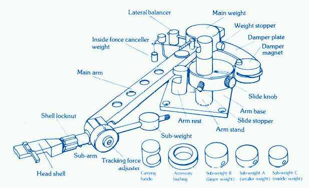

A shorter swing arm would place bearing D over the LP surface, but as long as guiding pivot P is able to cope with both vertical and horizontal motion (in the manner of a normal tonearm), bearing D only needs to pivot in the horizontal plane and can be kept compact.
Again, Dynavector style.
How short of a swing arm do you think that you could be comfortable with, directdriver?
I prefer the swing arm to be about 6 inches since that would clear the platter even if you use some unconventional low slung counterweight and would not touch the platter, except if you have a 14" platter. A 8" swing-arm is short but it's long enough to deal with warp records. Once again, I am thinking of the DV style, ie, guide-arm above swing-arm.
Over the next few days I will try to give you the tracking error figures for your 320mm diameter Thales circle, 218mm swing arm, and 43.32379mm guide arm geometry.
Your number must be derived from the Birch drawing. Just to let you know that's not my own drawing. It came from the original Birch patent that I rearranged and added pointers.
Here's the original Birch drawing from the patent.
An externally hosted image should be here but it was not working when we last tested it.
PS, I'm not much of a math person so I appreciate your lists and figures. Thanks for chiming in.
Last edited:
Man, what a lot to take in and respond to. I think I'm going to do this in small bites.
Jonathon, Thanks for all your work and for posting the tables. There's a lot to work with there.
I think the 320, 218, 43 numbers you've mentioned are from my arm. I had to recheck them and found I'd gotten a couple of them wrong and had set the pivot too close to the guide. That's been corrected and the correct numbers are:
Thales circle = 320 mm
Swing = 218 mm
Guide = 39 mm
If you'd be willing to run those numbers, I'd really appreciate it.
The photo illustrates a very good practical reason for not using a swing arm much over about 180 mm (7"). The mounting geometry is very restrictive so this 218 mm swing arm puts the cartridge right beside the platter and there's nothing to do about that.
After looking at Jonathon's tables, I ran a 274 mm EL conventional arm through a VE calculator. The Baerwald alignment showed the least tracking deviation at 1.3 degrees and other alignments went up to 2 degrees. In other words, despite the evidence in the tables of tracking error, it's in the region of two magnitudes less than a fairly long conventional arm and is probably beyond how accurately the stylus can be adjusted.
Attachments
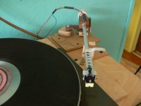
Hi guys,
Just a few remarks..
The deviations from tangency as calculated by Jonathan are WAAAAYYY below the achievable setup accuracy, at least if we're talking about human beings doing the setup.
Same for deviations defined by the accuracy achievable, - and I mean consistently - by cartridge manufacturers or their cantilever/stylus assembly suppliers.
In addition, the DIY LT arms I've seen here so far will yield a skating force, so the displacement of the cantilever stemming from that will be much larger than the theoretical max. deviation at the error maxima.
No idea why everyone is so rigidly adhering to the guide curve(D) having to be a circle segment. It can be anything. Just build a dummy arm with the target dimensions, mount a fine point pen at D(perpendicular, with paper underneath), aka the effective end of the guide arm, and move the cartridge(or a dummy) along the tangency points of the usable radius of the record. Use a succession of dots or move the cartridge along a rotating tangency guide bar. The pen will leave a guide line marking the required curve for a rigidly anchored guide point.
The (sorry, my) LT arm does not follow the Thales guide circle. Not just for the impossibility to achieve "perfect" tangency across the record, but mainly because the end of the guide bar isn't rigidly connected to the guide rail(magnetic coupling...) , the angle between both elements changing over the radius of the record. That alone needs to be compensated for...
The bearings in the LT arm do not allow for any slop, only the magnetic coupling does, - and for good reasons. Among those the near elimination of the fundamental arm-cartridge resonance peak in the lateral plane.
A peaceful and happy holiday season to all!
Frank
- Home
- Source & Line
- Analogue Source
- Angling for 90° - tangential pivot tonearms