The Birch geometry is based upon a Thales circle. As you state, in your model there is a deviation form the tangent (although small), that means that the curve is not a section of a Thales circle. Sorry, I have no idea what it is")
Ah I understand, The curve of green dots are not on a Thales circle but they are still 100% tangential to the spindle.
I'm trying to simplify my construction by using a circle pivot point instead of an ellipse. By using the circle pivot I get the tiny error, not from the original plot.
The biggest deviation swings from 0.08452 Degrees smaller to 0.235883 degrees bigger than tangent.
Second thoughts: how can there be a deviation from the tangent, if you rotate right angle triangles? How can the points drawn by the stylus sit not on a Thales circle under these cicumstances? Why are the calculated pivot points not on a circle but on an ellipse? I am convinced that you are fighting with rounding errors, and the apparent deviation from the tangent is an artefact.
The deviation only occurs because I'm using points on the circle. Not on the calculated rotated and translated right angled triangles.
The points that transcribes the line of the movement of these triangles form the arc of an ellipse. To follow this line mechanical is too complex for the function of a tonearm for me, it involves a cam.
So for me the closest approximation is a circle that is easy for me to implement. The circumference of the circle does not trace the the arc of the ellipse exactly, there is some deviance off the arc, but it translates into a very small error. So I can use the circle circumference as a track for my tonearm.
The Birch/Thales geometry starts with a circle and fits the triangle to it. I believe 2wice started with a triangle, let the resulting points fall where they may, and derived the circle/ellipse arcs from that. Another hint is that lines drawn through stylus-pivot points past the pivot in the 2wice plots don't converge to a point like X in the Birch drawing in post #799.
That brings me to a question, 2wice: There has to be a control mechanism that operates on the pivot arm to insure the stylus arrives at the correct point at the correct angle all the way across the LP. I used a sliding tube that pivots at point X for the arm I built. Frank Schroeder uses a magnet guide. Others have used clock motors/servos to turn a disc. I'm curious about what equivalent mechanism there is in your design or if you have come up with something that does away with that altogether. I understand that may be a part you'd rather not reveal at this time, but maybe later . . .
That brings me to a question, 2wice: There has to be a control mechanism that operates on the pivot arm to insure the stylus arrives at the correct point at the correct angle all the way across the LP. I used a sliding tube that pivots at point X for the arm I built. Frank Schroeder uses a magnet guide. Others have used clock motors/servos to turn a disc. I'm curious about what equivalent mechanism there is in your design or if you have come up with something that does away with that altogether. I understand that may be a part you'd rather not reveal at this time, but maybe later . . .
The Birch/Thales geometry starts with a circle and fits the triangle to it. I believe 2wice started with a triangle, let the resulting points fall where they may, and derived the circle/ellipse arcs from that. Another hint is that lines drawn through stylus-pivot points past the pivot in the 2wice plots don't converge to a point like X in the Birch drawing in post #799.
Good observation. 2wice's approach reminds me of member Esperado's design mentioned in post #225, except it's a servo design by detecting the laser at the spindle point under the platter from the pivot point which sits on a motorized rotating disc, hence all the converging lines don't form a single point. It may not exactly be Thales but it's still similar principle.
PS, I too am curious about 2wice's design mechanically. Hope see it in the future.
An externally hosted image should be here but it was not working when we last tested it.
One of the great things about this kind of arm is that the side forces can be nullified without using extra mechanisms so that the arm will sit motionless at any point on a blank disc.
There are a couple of possibilities that may do away with the tyranny of circles for the guide.
I am curious if you ever NOT use the guiding rod at all on your tonearm and letting the main pivot to track on its own, even for experiment? After reading Tom Bloem's thread about his fluid floating tonearm, I wonder if an arm like the Birch design can find tangency on its own...
I'm waiting for material to come from suppliers to build my arm, (3 month postal service strike here) if it does work I'll show. It does have a guiding rod with 2 equal lateral guiding forces. As the armtube angle changes, the guiding forces become unequal, as both side forces seek equilibrium it drives the pivot forwards. On paper anyway.
DD,
I just tried your suggested experiment and it went pretty much as I expected. Without the counter force provided by the control tube at point X, the arm just acted like a normal pivot arm and went out of tangent within the first track. There has to be a force paired with the force on the stylus to collapse the pivot arm forward and then, if the geometry is right, tangency results.
I believe Tom Bloem's explanation, as I read it, that longitudinal force resulting from stylus drag is what makes his arm work may not be the entire story. The system has mass and the water resists movement of the sphere through it creating a second force behind the pivot post. I think the combination of the two side forces, stylus drag, and friction between the post and guide cause the post to slide "downhill" along the guide so the arm moves across the LP. In other words, I see Bloem's arm as effectively a collapsing pivot arm meaning there have to be forces at both sides of the pivot and I believe that is the case. Bloem's arm is unique and interesting and I'm not commenting on the performance claims, just the explanation.
What kind of bearing would you use that is low in friction and at the same time strong enough to support the entire weight of the whole arm x 2?
You have 2 pivot points that must support and move effortlessly.. Maybe a deal breaker.. I don,t know.
I have a pair of Micro Seiki 505,s that I might sacrifice if I can,t find something else preferably instead of modding them.
Regards
David
You have 2 pivot points that must support and move effortlessly.. Maybe a deal breaker.. I don,t know.
I have a pair of Micro Seiki 505,s that I might sacrifice if I can,t find something else preferably instead of modding them.
Regards
David
David,
I'm not sure who you were addressing your question to, but in my arm I used inexpensive RC car ceramic hybrids. Each pair, 5/8" OD above and 3/8" OD below, is pre-loaded, which makes a huge difference in how well they move and eliminates chatter. All four are running sealed and with the factory lubricant. The top bearing, especially the primary pivot bearing, has both axial and radial loads so a deep groove or axial bearing would be an improvement there. Both lower bearings are mainly for radial loads and aren't as demanding. The arm is working well enough that I will very likely upgrade the bearings, meaning I'll spend more money.
Originally I thought the arm would require low compliance cartridges, but I've mounted higher compliance ones recently and they seem to work just fine.
In a previous arm, I used a sacrificial Pioneer arm with good results, but I don't think I would do the same with a good arm like a Micro Seiki unless it was already otherwise unusable or I was confident I could restore it if the project didn't work out.
Just a quick update.
I thought the first Birch style arm I built would work best with low compliance cartridges, but an M3D didn't sound right so I tried an AT95E at 2 gr and an AT120E at 1.2 gr. They worked beautifully so these arms are lighter and swing more freely than I expected.
I built a second arm with some changes in the geometry, the number of bearings and their arrangement, and, most importantly, the heim joint was replaced by a bearing/bushing combination. The new arm was designed to be simpler and lighter. It is lighter and will track with an ADC at 1 gr. Simpler I'm not so sure of.
Attachments
Thanks for the update, Doug. Very cool! Glad you're putting your creativity in refining and redesigning the guiding rod mechanism.
I wonder if using a tuning fork or chopsticks style would work for guide arm, similar to the bearing concept in a Simon York tonearm or what Mark Kelly did with his tonearm, to further simplify things?
------------------------------------
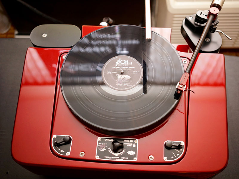
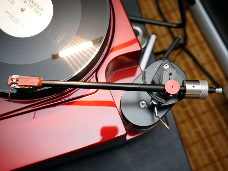
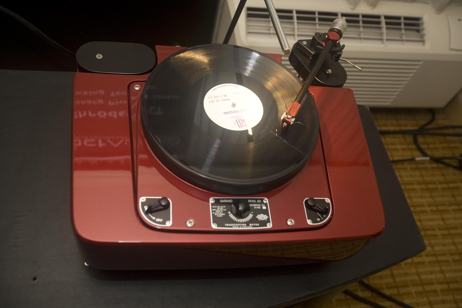
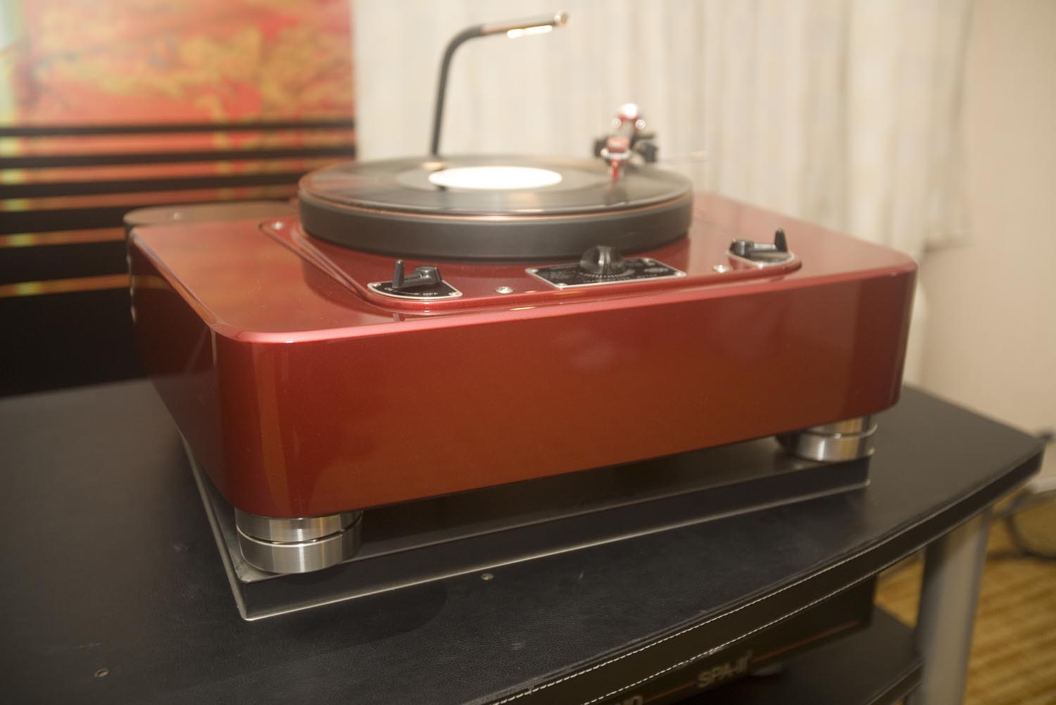
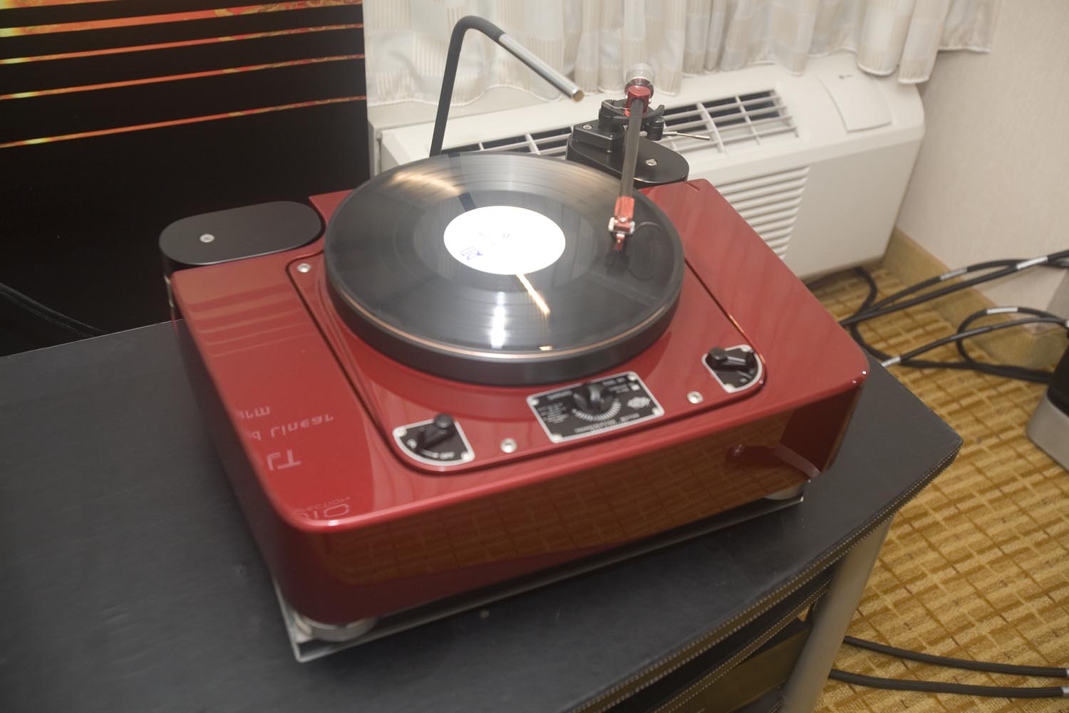
Here are some red hot eye candies, the new Schroeder LT in the recent RMAF 2014:


I wonder if using a tuning fork or chopsticks style would work for guide arm, similar to the bearing concept in a Simon York tonearm or what Mark Kelly did with his tonearm, to further simplify things?
------------------------------------
Here are some red hot eye candies, the new Schroeder LT in the recent RMAF 2014:
An externally hosted image should be here but it was not working when we last tested it.
Last edited:
phivates,
Measurements? Really? This is subjectiveville around here. So, all right, your question caught me unprepared. The new arm has an M91ED mounted at the moment and on the HiFi News LP it resonated at 13Hz laterally and through about an octave centered at 11 Hz vertically. Not bad by HiFi News standards, but high by VE standards. That may be high enough to effect the audible range and there's a possibility I'm hearing it. I'll try the AT95E. I didn't measure the first arm. Changing from the M3D to the AT95E was based on what I was hearing.
DD,
I hated to give up the Heim joint because it was so simple, but getting the right degree of free movement in any given specimen proved hard. The new purpose built guide is definitely better.
The dual chopstick/tuning fork guide will work, but there might be weight and alignment problems because it will have to be mounted on the arm. There's no reason not to try it, though. The pivot itself has to be a single rod to prevent binding. Two short rods mounted on a bearing might work, too.
This arm has a modified version of Simon York's azimuth control. His control won't transfer directly to this arm because on his arm it swings fore and aft as the arm moves vertically. On this arm, that control is stationary because it's mounted on a bearing instead of directly to the arm.
A super simple version of the Birch arm could be built using a combination of York's unipivot and the chopsticks - might result in a nicely damped arm.
That red 301 is stunning. Frank's LT looks really good there, right at home. My latest is on a 401, but neither are in the same class with the ones in the photos. I wish RMAF did a better job of indicating which equipment was going to be shown. I looked to see if Frank's LT was going to be there and planned to go if it was, but couldn't find any mention of it.
Doug: More requests for measurements (smile).
Have you attempted to quantify the amount of angular tracking error that you are getting from your present geometry?
And have you compared the angular error from a short guide arm_long swing arm (like what you have now) geometry with the error from a long guide arm_short swing arm geometry?
kind regards, jonathan
Jonathon,
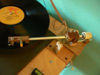
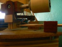
Back on pg 76, toward the bottom, at post #758 are photos of the rig I used to check for tracking error. On the first arm there was some error, but at the stylus, it would be tiny. I haven't checked the new arm, but just eyeballing it, the error is less. If that's true, I attribute it to the shorter swing arm combined with a longer wand rather than the shorter control rod, but I'm not sure about that. Unfortunately, there seem to be limits to how far the relative lengthening/shortening process can go. I hope I actually answered your question.
I'm still puzzling over the results to phivate's question. I can't get any correlation between the HFNRR test results and the answers in the VE calculators. VE gives me negative effective mass in which case we're into an interesting new realm of physics.
DD's question about Simon York's arm got my attention. I think if dual control rods were used and allowed to move in all three planes at the control pivot, the bearing compliment might be reduced to one ball bearing, one unipivot, and a magnet. I can't follow up on this right now - if I do, I'll be facing severe spousal disapproval.
DD's question about Simon York's arm got my attention. I think if dual control rods were used and allowed to move in all three planes at the control pivot, the bearing compliment might be reduced to one ball bearing, one unipivot, and a magnet. I can't follow up on this right now - if I do, I'll be facing severe spousal disapproval.
My original suggestion was really using the Yorke concept implementing on just the guiding mechanism ONLY and has to do with horizontal movement ONLY. It has nothing to do with the main arm but of course you can try that if you want. The Yorke idea is similar to Mark Kelly's duel chopsticks/tuning fork idea. Basically the hem joint is replaced by a stationary vertical post wrapped with a teflon sleeve and the horizontal guiding rod is tuning fork like or pair of chopsticks and meeting the vertical post so they slide around the teflon sleeve.
I do like your idea of using the Yorke design for all the functions, pivoting and guiding. But making it work might not be easy.... such as spending time away from the spouse.
- Home
- Source & Line
- Analogue Source
- Angling for 90° - tangential pivot tonearms