The point B pivot is a Heim joint. I know there's gonna be flak for that, but it does deal with all the functions of that point and operates smoothly. There are a multitude of options for implementing point B, some not involving a point B at all - the Heim joint was just simplest. Since the weight of the tube is carried by the primary pivot arm, the joint can be adjust so the tube barely touches the hole it rides in.
Great work, Doug! Finally someone actually built something from this thread! Yay!

Just to refresh people's memory of what "Point B" is, I am reposting the drawing of the geometry here:
An externally hosted image should be here but it was not working when we last tested it.
Do you think the guiding rod pointing towards B can be steel or ferrous and point B itself is a piece of round magnet below the rod? This way you can create a pivot that is noncontacting and less friction. Perhaps the use of magnet alludes to the Schroeder concept but it's different as Frank's arm creates a guiding path whereas this is a guiding point.
Excellent work again!
.
DD,
Thanks for your reply and for refreshing the drawing. That will be very helpful. That's the drawing I used for this project. I printed it to scale, went from there, and got lucky. That first copy has been scribbled and erased almost to transparency.
The friction at the Heim joint is minimal and there are other forces that, as far as I can tell, over ride it. As built, the tube is polished aluminum and the hole in the Heim joint ball has been polished. I want to test stainless steel and pyrex glass tubes, too.
A ferrous rod/tube or a ferrous section embedded in/on a non-ferrous tube might be constrained by a magnet pivot. I wanted to avoid the weight and the downward torque caused by the magnet since the bearings are being asked to deal with multiple simultaneous forces already. Frank's guide arm is much shorter than my guide rod so the moment around the horizontal plane bearings is much less. It shouldn't be hard to test, though. If it can be made to work, it would probably be an improvement since it would eliminate potential rattle if nothing else.
As Frank and Mark have established, Frank's concept and execution are very different from this. There is a family resemblance because of the pivoting arm, but beyond that, as you point out, the key is between path and point and that's not trivial.
This has been one of my favorite threads for a long time.
A ferrous rod/tube or a ferrous section embedded in/on a non-ferrous tube might be constrained by a magnet pivot. I wanted to avoid the weight and the downward torque caused by the magnet since the bearings are being asked to deal with multiple simultaneous forces already.
I understand the downforce concern. Perhaps placing the magnet above the rod or having two magnets above AND below the rod might alleviate the issue. Who knows, the magnetic force might also act as damping force a la Dynavector?
Anyway, I was thinking another way of doing the guiding rod/point. I know Mark did something similar in post #501, check picture.
An externally hosted image should be here but it was not working when we last tested it.
The idea I had in mind, before I saw Mark's picture, was inspired by the bearing used in the Simon Yorke tonearm. Make "B" as a thin vertical post or pin and put a teflon sleeve over it and then make the guiding rod shape like a tuning fork or like a pair of chopsticks and point them to B post in between. The teflon sleeve will have minimal friction without using any rotary bearing. In the end, it's still similar to Mark's idea.
An externally hosted image should be here but it was not working when we last tested it.
This has been one of my favorite threads for a long time.
Glad you enjoy it and I'm happy that it can help or inspire people to get some production out of this thread since I am such a slacker!
I would love to see more creations from forum members using similar concepts.
.
Another idea I thought of but abandonned when I came up with the new string arrangement was to have a single ferromagnetic rod which entered into a teflon tube overwrapped with an underhung coil of magnet wire. A small DC current through the magnet wire will pull the rod, counteracting the stylus friction. If the B pivot is just behind the coil the attractive force will also align the tube and rod.
BTW the damping as per Dynavector is eddy current damping. A non-ferromagnetic material is best because the field has to be really strong to get adequate damping so the attraction to a ferromagnetic material would overpower everything else.
BTW the damping as per Dynavector is eddy current damping. A non-ferromagnetic material is best because the field has to be really strong to get adequate damping so the attraction to a ferromagnetic material would overpower everything else.
magnet B
DD,
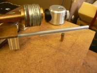
Thanks for prompting me to revisit the magnet point idea. I swapped a small magnet and ferrous wire attractor for the Heim joint and it shows real promise. Even this quick lash up sailed through the first side of "Time Out" with almost no problems and I liked the sound - very delicate and detailed.
The magnet induced torque on the guide tube is a major concern. The pivot arm has to be built very carefully to eliminate slack that allows the tube to drop toward the magnet. Given that, the magnet could be brought closer to the attractor to firmly lock the guide tube in place.
Mark's design in #510 was one I had in mind when I started this project, but I had it backwards: I was thinking of two uprights and one guide, which won't work because friction increases as the angle changes.
Mark: I really like the idea of the solenoid guide/damper, but I think it's beyond me.
I like Simon York's design and I think it might be possible to extend it so a unipivot Birch arm would be possible, which would eliminate four bearings and lighten the load on the remaining two. The magnet guide probably won't work with the unipivot, but with all the other guide possibilities, the trade off might be worth it.
Guys who are building very simple but elegant and effective arms inspired by Nanook, Vinyl Addict, and Soyuz are probably right to say an arm like this one is over-thought and unnecessarily complicated, but there's still the pleasure of figuring one of these things out and then building a successful version. It keeps me in my shop and out of my wife's hair.
DD,
Thanks for prompting me to revisit the magnet point idea. I swapped a small magnet and ferrous wire attractor for the Heim joint and it shows real promise. Even this quick lash up sailed through the first side of "Time Out" with almost no problems and I liked the sound - very delicate and detailed.
The magnet induced torque on the guide tube is a major concern. The pivot arm has to be built very carefully to eliminate slack that allows the tube to drop toward the magnet. Given that, the magnet could be brought closer to the attractor to firmly lock the guide tube in place.
Mark's design in #510 was one I had in mind when I started this project, but I had it backwards: I was thinking of two uprights and one guide, which won't work because friction increases as the angle changes.
Mark: I really like the idea of the solenoid guide/damper, but I think it's beyond me.
I like Simon York's design and I think it might be possible to extend it so a unipivot Birch arm would be possible, which would eliminate four bearings and lighten the load on the remaining two. The magnet guide probably won't work with the unipivot, but with all the other guide possibilities, the trade off might be worth it.
Guys who are building very simple but elegant and effective arms inspired by Nanook, Vinyl Addict, and Soyuz are probably right to say an arm like this one is over-thought and unnecessarily complicated, but there's still the pleasure of figuring one of these things out and then building a successful version. It keeps me in my shop and out of my wife's hair.
Attachments
Of course your wife is responsible for her own hair. My wife is on me for my bushy Irish eyebrows. As for your arm, I must say thank you for demonstrating, again, that we the people can contrive something that works without millions or billions or trillions of dollars not to mention decades invested. We're looking at Fall and Winter again and I swear I'll submit my homage to the B-J arm and its progeny before 2015. I make no guarantee that the gurus will like it. Most of them dislike Shure M44 carts to say the least.
DD,
Thanks for prompting me to revisit the magnet point idea. I swapped a small magnet and ferrous wire attractor for the Heim joint and it shows real promise. Even this quick lash up sailed through the first side of "Time Out" with almost no problems and I liked the sound - very delicate and detailed.
The magnet induced torque on the guide tube is a major concern. The pivot arm has to be built very carefully to eliminate slack that allows the tube to drop toward the magnet. Given that, the magnet could be brought closer to the attractor to firmly lock the guide tube in place.
The problem with the magnetic guide is that the tracking error varies with the friction of the stylus. The magnet introduces a new eigenfrequency as well, since the coupling between the magnet and the guiding rod is not stiff.
phivates,
Good to know you're still at the party. Good luck with the B-J clone.
Have you checked out preloaded bearings? GMN Spindle Ball Bearings / Technology / Preload And Bearing Arrangement
Or check out the Schroeder LT patent drawings DD posted a ways back.
alighiszem,
Thanks for your reply.
I expected the loose coupling between the guide and the magnet to introduce tracking error distortion or resonances (eigenfrequencies - what a great term. I had to look it up) especially bass notes or piano chords, and was surprised to not hear either. I know that's subjective and measurement might show something different.
One of the great things about this kind of arm is that the side forces can be nullified without using extra mechanisms so that the arm will sit motionless at any point on a blank disc.
the arm will sit motionless at any point on a blank disc.
That feature alone is already worth all the effort! Thanks for confirming that. I believe that has the leg up over Garrard Zero 100 style arms that the extra pivot point is at the headshell.
Guys..... are probably right to say an arm like this one is over-thought and unnecessarily complicated, but there's still the pleasure of figuring one of these things out and then building a successful version.
I understand the complication. But I want to remind people that when I started out this thread, I was struck by the inventiveness of the original Thales tonearm and its root in the Garrard Zero 100. At the time I thought of implementing such concept on an existing tonearm, preferably inexpensive, it's simplicity itself without resorting to linear bearing, air bearing, fish pump, etc... I had simplicity in mind that adding an extra pivot at the headshell and coming up with an inventive way to make the guiding mechanism is DIY-able and inexpensive. This is all before, inevitably, I learned about skating force, the Birch geometry, Van Eps, strings, magnets, etc... and coupled with the release of Schroeder LT, Thales Easy, and the rise of Cantus clones, etc... They all contribute to the evolution of tangential tracking. They changed the game.
Even if I were to roll up my sleeves to get to work, I never intended to build from scratch as there are so many readily available tonearm parts on eBay at cheap price. But I understand the appeal of building from scratch but I'm an incurable tweaker so modifying is more fun for me. Since I have piles of pivot tonearm parts, the idea is to mod some of them into tangential trackers. There's also an aesthetic choice that I never disclosed before, that is, I hate the look of parallel arms crabbing across the record. The elegance of pivoting the arm across the record is always more appealing to me and I can't explain why. I just want to lift and swing the arm over the record and play music. Products like the Clearaudio Statement with sliding base and over-mechanized pillars and bridge borders on the obscene and really turns me off. What I want is a conventional pivot arm with the benefit of tangential adjustment so in the end, for people with limited means, modding an existing arm in the Thales Easy or Garrard Zero 100 style is still alluring. Of course, the forward thinking of Frank Schroeder is always ahead of the game and its quasi-Birch design added another option.
In the end, I just want this to be a fun thread, build or not build.
Happy listening!
-------------------------------------------------------------
PS, I would still like to revisit this design in the future:
An externally hosted image should be here but it was not working when we last tested it.
An externally hosted image should be here but it was not working when we last tested it.
An externally hosted image should be here but it was not working when we last tested it.
An externally hosted image should be here but it was not working when we last tested it.
I made a quick attempt at the over/under magnet arrangement DD suggested and - to quote Mark Kelly - "ran afoul of Earnshaw." With an absolutely rigid mount for the guide rod, it might be possible, but probably not worth the effort.
alighiszem: After the dual magnet experiment, I went back to the Heim joint. Starting with the first cut, it was obvious the dynamics had improved significantly so you're correct that tight coupling at the B point is essential. Kind of a shame about Earnshaw and the dynamics. I had hopes the frictionless guide.
DD: My allergy is bearings on headshells. Apologies phivates. I thought it might be possible to eliminate those bearings by moving everything to a parallelogram behind the tonearm. Something like the upper and lower A arms on a car suspension, but horizontal. I still want to try that, but first I had to decipher the Birch geometry and then build something based on it to see if the leading arm would do its job. Now to design the trailing arm. There are a couple of possibilities that may do away with the tyranny of circles for the guide.
One of the great things about this kind of arm is that the side forces can be nullified without using extra mechanisms so that the arm will sit motionless at any point on a blank disc.
Doug, I suppose I proved here, that there must be a skating force with these construction.
Gabor
No apologies Doug I'm also leery of bearings at play so to speak right on top of the stylus. On the other hand I'm reasonably sure that some or all of what I'm planning will contribute noises of some kind. Fortunately we have the drag of the stylus taking up lash, right? And we've all gone on to M3D Shure compliance levels after that romance with extreme trackability. Wrong? Flux Valve Pickerings?
phivates,
An M3D could push a brick across an LP. If I were doing a B-J clone, low compliance and 2 - 4 grams would be on the menu.
alighiszem,
I'm not saying you're analysis of your drawing is wrong. I'm just saying you could take it farther. For instance, in the Birch picture on pg 77, the pivot arm and the tonearm are at more than 90 degrees to each other. That's important because if they are at 90 degrees, the arm may very well not work at all.
My allergy is bearings on headshells.
I understand allergy: headshell bearing is your peanut butter. Everybody has philosophical decisions. Mine is airpump.
From a DIY standpoint, making a bearing on the headshell is much easier than most of the projects on here.
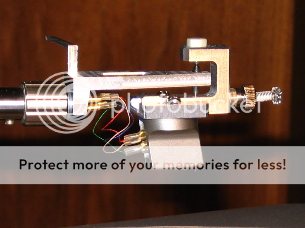
The RS Lab style headshell is one option as it only has two spikes or two contact points so if executed right chatter or noise should be minimal. There's reported mechanical problem but I think that can be addressed. But there are still many satisfied RS arm users out there. Building it on an aftermarket detachable headshell allows flexibility and is reversible for many available tonearms, the SME 3009 style arm or many Jelco models.
I must add again that the RS Lab headshell does NOT self align and is NOT a tangential tracker. It needs a guiding mechanism to be qualified as an LT arm.
- - - - - - - - - - - - - - - - - - - - - - - - - - -
Although I posted many pictures on post#44, here are some more examples below and of course none of the image shows any guiding mechanism so it's up to the DIYers to use their creativity!

I think the bottom spike area can be a small reservoir that allows a dab of silicone fluid damping. Just another idea.


Dynavector "split-plane" arm with pivoting headshell!


47LABs stated that somehow it decouples cartridge vibrations from tonearm itself. Pivot point being exactly in line with stylus, it is not understandable, how it should be able to decouple them from the point of basic physics. A very strange device, as well as many of 47LABs ideas.
- Home
- Source & Line
- Analogue Source
- Angling for 90° - tangential pivot tonearms