Hello,
I am new here--what a great fountain of info. I found Sir Hall's Pentonlector amplifier circuit on the web about 5 or 6 years ago http://www.radioconstructors.info/sdh/pentonlector/circuit.jpg and since then have put the circuit together a few times trying out different output iron. I could never quite zero in on the sound I had hoped to get. The circuit still remains interesting, and recently I have revised the circuit to exclude the transformer and include a two transistor current source load. The results in my humble opinion are worth continuing on with. The current source seems to be a decent load for the amp, and one interesting feature is that R4 sets the midpoint voltage which seems to remain stable. I left this amp turned on accidently overnight the other evening, and all voltages were stable the next morning. I will try to post the circuit diagram for those interested. Apologies if it doesn't attach properly.
I am new here--what a great fountain of info. I found Sir Hall's Pentonlector amplifier circuit on the web about 5 or 6 years ago http://www.radioconstructors.info/sdh/pentonlector/circuit.jpg and since then have put the circuit together a few times trying out different output iron. I could never quite zero in on the sound I had hoped to get. The circuit still remains interesting, and recently I have revised the circuit to exclude the transformer and include a two transistor current source load. The results in my humble opinion are worth continuing on with. The current source seems to be a decent load for the amp, and one interesting feature is that R4 sets the midpoint voltage which seems to remain stable. I left this amp turned on accidently overnight the other evening, and all voltages were stable the next morning. I will try to post the circuit diagram for those interested. Apologies if it doesn't attach properly.
Attachments
Member
Joined 2009
Paid Member
Hello,
I'd be glad to list the voltages after about 10 minutes of warm up time. And, I'd like to humbly acknowledge the true creator of this circuit the late Sir Douglas Hall, whose work I admire very much. All I did was modify an already elegant circuit. I measure with Vcc at +32VDC:
15.7 V at midpoint m (this moves up or down with change in R4)
Q1 collector/ V1 K at 2.5v (I thought this may cut off the tube but it works fine)
V1 screen at 31.8 V
MPSA18 collector at 16.7 V
2N3055 emitter at 16.1 V
MJ2955 base/ V1 plate at 15.0 V
there is approx 800ma of quiescent current flowing. As Sir Hall indicated in his original article, there is tremendous feedback established via the Q1 V1 interface. I have not yet substituted any parts for different ones, except origially I had a 2N3053 where the MPSA18 sits, however the MPSA18 works much better. I wish I had more test equipment. As I sat with a cold one the other night and pondered this circuit's merits, I wondered if the MPSA18 was acting like a common base amplifier which would apply a 180 degree out of phase signal on the top of R3. If it does, I don't see how it could possibly hurt anything by doing so---at any rate, without trying to describe the sound, I just like it.")
I'd be glad to list the voltages after about 10 minutes of warm up time. And, I'd like to humbly acknowledge the true creator of this circuit the late Sir Douglas Hall, whose work I admire very much. All I did was modify an already elegant circuit. I measure with Vcc at +32VDC:
15.7 V at midpoint m (this moves up or down with change in R4)
Q1 collector/ V1 K at 2.5v (I thought this may cut off the tube but it works fine)
V1 screen at 31.8 V
MPSA18 collector at 16.7 V
2N3055 emitter at 16.1 V
MJ2955 base/ V1 plate at 15.0 V
there is approx 800ma of quiescent current flowing. As Sir Hall indicated in his original article, there is tremendous feedback established via the Q1 V1 interface. I have not yet substituted any parts for different ones, except origially I had a 2N3053 where the MPSA18 sits, however the MPSA18 works much better. I wish I had more test equipment. As I sat with a cold one the other night and pondered this circuit's merits, I wondered if the MPSA18 was acting like a common base amplifier which would apply a 180 degree out of phase signal on the top of R3. If it does, I don't see how it could possibly hurt anything by doing so---at any rate, without trying to describe the sound, I just like it.
Member
Joined 2009
Paid Member
I Q3 see it acting as a servo for Q2, keeping some control over the current, making the top half of the circuit a constant current source. You might be interested in a simple but interesting 'upgrade' to your circuit by converting this current source to an Aleph current source. Go and have a look at the Zen amplifier papers by Nelson Pass: http://www.passdiy.com/pdf/zen-ver2.pdf
here you will find the reason behind my interest in your circuit - we appear to be treating similar ground but I never got any further with this than some initial thoughts....
http://www.diyaudio.com/forums/tube...g-triode-fet-complementary-feedback-pair.html
here you will find the reason behind my interest in your circuit - we appear to be treating similar ground but I never got any further with this than some initial thoughts....
http://www.diyaudio.com/forums/tube...g-triode-fet-complementary-feedback-pair.html
Last edited:
Thanks Bigun,
Wow, I have visited Pass DIY but never knew there was such extensive info on his current sources. The Aleph design is extremely interesting. Almost everything I was sitting there wondering about is explained very well. Dang, it seems that every time I work with Mosfets though, I blow 'em up! In trying to make the Hall amp work, I first found 2 transistor current source on an EDN link from Discover Circuits. Later I found good info from Rod Elliot's site. And have wondered how the dynamic impedance of the current source translates multiplied by the Q1 beta as the V1 plate load. It would be an odd mix indeed to have tube/bipolar/mosfet marriage. The only reason I have stuck with the Hall amp is it's utter simplicity, high input impedance and decent sound. It does have servo action, in that, if the Q1 collector current increases excessively, it will increase the tube bias accordingly. I have a lot to learn, and more test equipment is definitely needed, but will also need to spend more time at Pass DIY. On your circuit, have you got one up and running? Thanks again for the heads up on the Zen current sources.
Terry
Wow, I have visited Pass DIY but never knew there was such extensive info on his current sources. The Aleph design is extremely interesting. Almost everything I was sitting there wondering about is explained very well. Dang, it seems that every time I work with Mosfets though, I blow 'em up!
In trying to make the Hall amp work, I first found 2 transistor current source on an EDN link from Discover Circuits. Later I found good info from Rod Elliot's site. And have wondered how the dynamic impedance of the current source translates multiplied by the Q1 beta as the V1 plate load. It would be an odd mix indeed to have tube/bipolar/mosfet marriage. The only reason I have stuck with the Hall amp is it's utter simplicity, high input impedance and decent sound. It does have servo action, in that, if the Q1 collector current increases excessively, it will increase the tube bias accordingly. I have a lot to learn, and more test equipment is definitely needed, but will also need to spend more time at Pass DIY. On your circuit, have you got one up and running? Thanks again for the heads up on the Zen current sources.Terry
Thanks Bigun
Finally had a little time to try out the suggestions you posted re: Nelson Pass current sources. I altered the CCS by splitting the 4.75K resistor and adding a bootstrap capacitor ala Pass. There is a great big difference in the output now. More clarity, far better bass. Mind you, this amp would require efficient speakers. There is something here worth working on further. I don't say its the ne plus ultra or anything but it has musicality. Also trying to figure out the cathode resistor, its function when changed causes the quiescent current to go up or down.......don't really get that yet, as I thought the CCS had command and control over the Iq. The current setup is happily playing some 70's music on the workbench (that is-----the inglorious basterd of workbenches!!)
Well.......cold beer here..........as the Stan Ridgway song says: "I'll do it tomorrow!"
Have a good one Bigun
Member
Joined 2009
Paid Member
Wow, you don't hang around, good to see you making progress.
I'm still playing with metal work. I don't enjoy that as much as I should so I'm trying to get the amplifier hardware sorted out before I play with the fun bits. Today I was breaking drill bits, filing and hacking bits around to install a volume potentiometer on the front panel of each box (I'm making 4 boxes - so I can play with 4 different designs).
I have set myself the challenge of using junk box parts, no orders to Digikey allowed. I can't think of a good reason for this, must be some truth in the old adage about 'mad dogs and Englishmen...'
But my junk box has a couple of Russian Nuvistors
I don't uderstand the reason for the complexity of the Pass modulated current source outputs
the output stage in this sim shows a simpler approach with the same push-pull 50% efficient Class A result (sized for headphone amplifier)
the output stage in this sim shows a simpler approach with the same push-pull 50% efficient Class A result (sized for headphone amplifier)
...
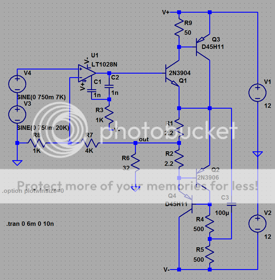
...Q1,3 cfp has similar current gain but lower distortion than the complemetary Darlington/"Diamond" output
Q2,4 is a feedback ccs with a twist - tapping the current sense resistor R1,2 in the middle gives push-pull Class A output, ~170mA quiescent - >300mA pk output but does give hard current limit at 2x quiescent...
Member
Joined 2009
Paid Member
There are many different ways to 'skin the cat' and obtain a PP output. Nelson has explained his method well, tested it and documented it so that it is accessible to the DIYer regardless of skill level.
I started simulating the circuit you posted a few months back, although I had the modulated CCS on top and the CFP on the bottom and I put a resistor in series with C3 to control the balance between upper/lower current swing rather than split R4/5 - I like your split R4/5 approach. I like CFP too, I had the modulated CCS drive a CFP so that the output had a CFP at both top and bottom. The circuit has never been built though.
I started simulating the circuit you posted a few months back, although I had the modulated CCS on top and the CFP on the bottom and I put a resistor in series with C3 to control the balance between upper/lower current swing rather than split R4/5 - I like your split R4/5 approach. I like CFP too, I had the modulated CCS drive a CFP so that the output had a CFP at both top and bottom. The circuit has never been built though.
Nice looking circuit jcx
Well, have not gotten into push-pull circuitry for a long while, but I see your point.......I guess what interests me is preserving as much as possible the signal without chopping it in half, inverting the phase, etc. It was very interesting and enlightening reading Pass. The analogy of the operation of single ended type amps to air pressure (asymmetry) was very interesting. Its not that one way is any better than the other. The beauty of Mr. Pass's CCS designs to me are the fact that the load allows the output device to function to the extremes of its capability----until someone invents an output device that perhaps operates on some other principle. With the devices we have to work with, those designs are as advanced as it gets. As far as this little Hall amplifier goes, its just fun to see what can possibly squeezed out of it performance-wise. Its fun---no more and no less.
Bigun, I'll be watching for your progress--good luck
Terry
Q2,4 is a feedback ccs with a twist
jcx,
I asked this in the other thread, but was a bit late. Are there any requirements or precautions to keep this feedback CCS stable? I was thinking of the relative fT of the transistors Q2 & Q4, but I'm sure there are other considerations as well.
Member
Joined 2009
Paid Member
Bigun, I'll be watching for your progress--good luck
Terry
Thanks for the good wishes ! -- this weekend I hope 'Bigun's Botch Up' amplifier will progress a bit further, perhaps enough to see the power supply come to life.
Whats nice about the JCX circuit, though its upside down compared to the first,
is that you've split the current sensing load sensing resistor R1+R2. And hold the
sum of drops to a constant voltage. You've tricked the lower circuit to become
an active anti-compliment of the upper, power is doubled, and single-endedness
is preserved. Now if you just throw the tube back into the mix, preferably a Triode
or Pentode strapped to lower plate resistance as-if Triode, UL, CFB, or Schade...
The first circuit looks a lot like Triodlington, and its a shame a Pentode was used
here, as the transistor can't benefit from Mu feedback with the screen in the way.
R2 maybe should been a stack of diodes with a bypass cap and/or additional
current from outside the Mu feedback loop to keep the diode voltage constant...
As you've pointed out, the current in R3 is already well managed.
Last edited:
I had thrown this plan together for Keantoken's edification into tubes.
Given him some 6dj8 earlier, needed a safe project to demonstrate Mu.
It also shows exactly what I mean about the Triodlington, though we
both draw a Sziklai pair. My thought was so cathode bias won't waver
with the base voltage of the power transistor. Though the Darlington
version uses few less parts, the bias voltage is much less controllable.
I think you have it right that this should be Sziklai.
Also PNP often have more linear beta than NPN, I'm not sure why...
But imagine a 2N3055 in Sziklai with my Q1. The power transistor base
current is hidden into the total Sziklai current, and the voltage effect
of that total current overwatched by Mu. Add your load at the top,
but with a split sense resistor like JCX showed...
Currents here are a little small for Q1 to drive a 2N3055, but thats
mostly cause I designed the circuit around an absurdly low voltage
and a very small triode... The Mu feedback and the diode bias were
the two things you should steal from this picture if nothing else...
Attachments
Last edited:
Hall amp-with changes
Good day,
There have been some changes implemented which are reflected in the modified circuit diagram. This rendition retains the simplicity, and thanks to Bigun for pointing me toward Mr. Pass's current sources. I wanted to increase the power supply so a suitable 36 vac toroid was found and is bridge rectified, followed by a pi filter. The 50 mH choke is a Hammond choke I rewound to provide a more even layering. I made two of those, and it works really well, so perhaps a stereo version is in the works. The little RS 1285 speaker is unbaffled, and I'll leave it as long as I can stand it---this amp will do bass, so I'll drag a better one in as soon as I am satisfied the whole thing will not go up in smoke Also---the screen supply was split and seems to work fine. So far so good.....not bad
Terry
Good day,
There have been some changes implemented which are reflected in the modified circuit diagram. This rendition retains the simplicity, and thanks to Bigun for pointing me toward Mr. Pass's current sources. I wanted to increase the power supply so a suitable 36 vac toroid was found and is bridge rectified, followed by a pi filter. The 50 mH choke is a Hammond choke I rewound to provide a more even layering. I made two of those, and it works really well, so perhaps a stereo version is in the works. The little RS 1285 speaker is unbaffled, and I'll leave it as long as I can stand it---this amp will do bass, so I'll drag a better one in as soon as I am satisfied the whole thing will not go up in smoke
Also---the screen supply was split and seems to work fine. So far so good.....not badTerry
Attachments
Next iteration
Good day
Well, the amp keeps evolving as to better parts. Finally found my box of On Semi MJ15003G and replaced the rather basic 2N3055 with one of those. R4 adjusted to 1K R5 to 4.7K. I don't know--the amp seems a lot faster. mids are very likeable when the amp's voltages all settle in. Replaced output caps with 5 parallelled 1000uF Nichicon Muse, 220uF Muse on the bootstrap. Very noticeable and pleasing improvement. Will get some more KZ for the V1 screen. Yes, I will commit this design to a stereo set on a chassis as soon as time permits. Photos will appear for anyone interested. Man, this has been a fun little journey----now all I am going to need are some speakers Which is a whole other problem--need cheap/fast/good bass/efficient/small size Any ideas?
Terry
Good day
Well, the amp keeps evolving as to better parts. Finally found my box of On Semi MJ15003G and replaced the rather basic 2N3055 with one of those. R4 adjusted to 1K R5 to 4.7K. I don't know--the amp seems a lot faster. mids are very likeable when the amp's voltages all settle in. Replaced output caps with 5 parallelled 1000uF Nichicon Muse, 220uF Muse on the bootstrap. Very noticeable and pleasing improvement. Will get some more KZ for the V1 screen. Yes, I will commit this design to a stereo set on a chassis as soon as time permits. Photos will appear for anyone interested. Man, this has been a fun little journey----now all I am going to need are some speakers
Which is a whole other problem--need cheap/fast/good bass/efficient/small size Any ideas?Terry
Thanks picowallspeaker
Actually, parallelled 16 ohm speakers had crossed my mind as Apex Jr has some Cerwin Vegas on the cheaps. I have a bunch of mdf laying around. Perhaps an mtm or some sort of dynaco a50 ish clone--may be this kind of post needs to be in another thread --thanks for your input'
Terry
Actually, parallelled 16 ohm speakers had crossed my mind as Apex Jr has some Cerwin Vegas on the cheaps. I have a bunch of mdf laying around. Perhaps an mtm or some sort of dynaco a50 ish clone--may be this kind of post needs to be in another thread --thanks for your input'
Terry
The amplifier gains form
Good evening,
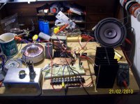
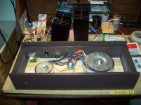
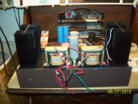
I have finally had time to make some progress on a stereo version of this amp. Here's a couple of photos with some of the parts not yet permanently secured, the power supply starts in the bottom and the PS chokes and PS output caps reside on the top deck along with the heatsinks. The relay circuit is only for allowing the tube fils to light up for about 30 seconds before establishing B+, as I want the midpoint voltage to be right at half supply instead of rising high and settling back down. There will be some L bracket off the sinks for the tubes, and the output caps will have to go somewheres. The actual circuit components are so few, they will fit on a small card right at the output transistors. There will be a back panel that supports signal in and speaker outs, and the sides will receive some small finished red oak panels. There'll be a screened cover if I can swing it. Right now it is somewhat a mess, but at least the chassis work is done, which I like least. I'll let you know how it all works out, hopefully not too many weeks hence.
As they say on ebay, "thanks fer lookin!"
Cheers,
Terry
Good evening,
I have finally had time to make some progress on a stereo version of this amp. Here's a couple of photos with some of the parts not yet permanently secured, the power supply starts in the bottom and the PS chokes and PS output caps reside on the top deck along with the heatsinks. The relay circuit is only for allowing the tube fils to light up for about 30 seconds before establishing B+, as I want the midpoint voltage to be right at half supply instead of rising high and settling back down. There will be some L bracket off the sinks for the tubes, and the output caps will have to go somewheres. The actual circuit components are so few, they will fit on a small card right at the output transistors. There will be a back panel that supports signal in and speaker outs, and the sides will receive some small finished red oak panels. There'll be a screened cover if I can swing it. Right now it is somewhat a mess, but at least the chassis work is done, which I like least. I'll let you know how it all works out, hopefully not too many weeks hence.
As they say on ebay, "thanks fer lookin!"
Cheers,
Terry
Attachments
Power supplies built and tested
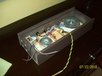
Some progress on the amp. Two 15VAC heater supplies, relay delays B+ turn-on for 30 seconds (thanks to Bill Bowden's Hobby Circuits page for a very workable and stout relay delay circuit). Also switched (from the relay) 12VDC for the LED indicator to glow yellow during warmup, switching to green at power up. Got some Panasonic PS caps from Digi-Key in order to give the PS its best shot, and to unclutter the top deck as much as possible. All appears to be shaping up. Now I find my thoughts turning to speakers, maybe line arrays, since efficiency is important, and also spending time experimenting with preamp/phono stages. Hopefully this will be a satisfactory amplifier, it sounded very good on the breadboard-even with cheapie speakers. I hope you have a good weekend.
Terry
Attachments
- Status
- This old topic is closed. If you want to reopen this topic, contact a moderator using the "Report Post" button.
- Home
- Amplifiers
- Solid State
- An initial watt revision of a classic little amp