my personal favorite is the citation 12 mosfet, modified with a t-driver stage and complementory mosfets.
I also modified the jlh1969 with mosfets and it sounds and simulates very well over the bjt version.
I don't know about that. Junction capacitance of those transistors isn't huge so any "delay" is likely in the radio frequency. the likely problem I see with such a large base resistor is DC offset. But then it is kind of balance between the upper and lower pairs so big deal.
I also modified the jlh1969 with mosfets and it sounds and simulates very well over the bjt version.
subwo1 said:The 62k input resistors do delay the input, but I think that since they are before the feedback loop, they don't add any real distortion to the signal.
I don't know about that. Junction capacitance of those transistors isn't huge so any "delay" is likely in the radio frequency. the likely problem I see with such a large base resistor is DC offset. But then it is kind of balance between the upper and lower pairs so big deal.
I appreciate the thoughts, millwood. I grant that you are onto something since the base does have a capacitive tie-in with the collector and emitter. But since simulations do show drastic improvement in circuit stability with this configuration, maybe the effect I am counting on is greater than the one you mentioned. Is the jury still out?
My, this is an excellent thread.
Hi thoriated,
I don't know of the 6K11 for gm, Ra etc; I trust it is okay with the widely varying heater cathode potentials.
A lower impedance at V1b anode might give a tiny improvement, say with a 10uF to the 0V line. Does V1b anode actually need the lower potential and impedance because it is not being used to generate differential anode potentials; could the anode not go directly to the +Vcc line ?
I presume C5 is a bootstrap - possibly 10uF. That is so neat !!! Like a curent source for the V1a cathode/output drive chain.
Can I suggest that you also split R2, and bootstrap the centre tap from pin 4 - V1a cathode with say 2.2uf to improve large amplitude linearity.
This is something I first did over thirty years ago with 12AU7s; each was wired common cathode + common anode with direct second grid connection to the first anode. Each 12AU7 drove two KT88s (6550) in a parallel push-pull hybrid for 100W hi-fi, and the grid to grid distortion was less than 0.1% before NFB ! That amp is up in my roofspace somewhere; the valves must be worth a bit now. They don't manufacture transformers like that any more.
Hi liemanauw,
Nice circuit, but I could forsee a disadvantage at high frequencies when compared to Jam's, especially with such a low input pair tail current. At 80Vdc, Q3 onwards could be 2N5401 and 2N5550 as in subwo1's diagram.
When I construct a current mirror I often a insert a LED or two 1N4148s between the base and collector to establish a steady 1.5 to 2.5 Vce on the 'passive' device; this is so that the mirror is not slow under load induced NFB correction wrt input.
It is however unlikely that any improvement would be observable from the extra components if the amplifier circuit also uses a Miller C.dom which, by its very nature, already limits performance.
Hi Jam,
I knew that was coming.
My circuits are the subject of an article being published this summer in Electronics World. Will post then. You could think of the humble JLH-69 with a mirrored differential input stage, direct coupling and twin power rails - 7 transistors. Good for 30W in basic form, or 100W plus in my more powerful and more efficient class-A, but it is also more complex.
Sound ? It doesn't have one ! It just amplifies; the rest is up to source and loudspeaker. The original was good for its time with better hf clarity than valves, but with a curious singleton input modulation that varied with amplitude and frequency. It was better than many class-Bs though, including some that are supposedly blameless. My additions bring the circuit up to date with better than 0.01% THD.
Must get back to my soldering iron
Cheers ............ Graham.
millwood said:my personal favorite is the citation 12 mosfet
I second that... My favorite topology is a quasi-complementary pair.
I know they are old fashioned and complementary outputs are better but there's something about P half / N half "copying" that I think is neat.
I'd like to build an amp with the P/N halves of the output stage being near copies of eachother. I just haven't figured out how to drive it properly... I had a couple of designs I Pspiced but nothing with any good specs.
Hi, Graham -
Thanks for the feedback. You raise some very good points, which I'll attempt to respond to below.
Actually, when I started deliberately varying the mains voltage (dropping it by 20%) last weekend, I found that there was about a 50mV shift of the DC offset due to changing gm, etc. As a result, I have decided to apply regulated DC to the filament in the final design which should remove this problem.
Good question. Until just recently, the V1b anode did go directly to the +Vcc line. But the other contributing sensitivity to dc offset shift with varying mains voltage (supplies not regulated, of course) was the fact that as the supply voltage changed, the relative bias points between V1c and V1b would change slightly, causing another 50-100 mV dc offset shift when the mains voltage was dropped 20%. The divider as shown removes 80-90% of that sensitivity, since both halves of the diff amp now track at almost the same bias point with much less sensitivity to supply voltage variations. Adding the cap you mention is an option if I stay with this approach. However, I'm shortly going to evaluate a dedicated supply at half the potential of the V1c supply (actually doubling the latter) in order to gauge its relative performance in this regard.
Thanks. Too bad there aren't any minority carrier tubes")
Thanks for the suggestion. I'll put that in my queue of things to try. I am finding some limitation in this particular area, especially since I am potentially asking the V1c plate to swing up to or even over 120Vp-p under some circumstances which causes excess distortion. Btw, last night, I decided that I will try supplying V1c from a voltage doubler (which would produce just under 400VDC) and connect the negative leg of the voltage divider to a voltage tripler I've already prototyped (-600Vdc). Besides improving AC linearity, what I hope to do here is to reduce or eliminate the effect of grid current on any useable signal swing, something a cap will not directly affect. As the circuit now stands, when the peak negative signal swing at the V1c plate starts going greater than about 45V or so, the grid current draw potential shift is effectively averaged across C3 and can result in a large signal (near projected output stage clipping) dc offset shift of several hundred millivolts. My preliminary estimation is that doubling the supply to V1c will reduce that to perhaps 50mV or less. I should mention that with the divider chain from V1c, its plate will never see the full 400Vdc even during warmup; only about the 330V it is rated for, so I figure I should be ok there. There will be some sort of passive voltage clamping during warmup for V1b, c cathodes and V1a grid in the final circuit.
Thanks for the feedback. You raise some very good points, which I'll attempt to respond to below.
I don't know of the 6K11 for gm, Ra etc; I trust it is okay with the widely varying heater cathode potentials.
Actually, when I started deliberately varying the mains voltage (dropping it by 20%) last weekend, I found that there was about a 50mV shift of the DC offset due to changing gm, etc. As a result, I have decided to apply regulated DC to the filament in the final design which should remove this problem.
A lower impedance at V1b anode might give a tiny improvement, say with a 10uF to the 0V line. Does V1b anode actually need the lower potential and impedance because it is not being used to generate differential anode potentials; could the anode not go directly to the +Vcc line ?
Good question. Until just recently, the V1b anode did go directly to the +Vcc line. But the other contributing sensitivity to dc offset shift with varying mains voltage (supplies not regulated, of course) was the fact that as the supply voltage changed, the relative bias points between V1c and V1b would change slightly, causing another 50-100 mV dc offset shift when the mains voltage was dropped 20%. The divider as shown removes 80-90% of that sensitivity, since both halves of the diff amp now track at almost the same bias point with much less sensitivity to supply voltage variations. Adding the cap you mention is an option if I stay with this approach. However, I'm shortly going to evaluate a dedicated supply at half the potential of the V1c supply (actually doubling the latter) in order to gauge its relative performance in this regard.
I presume C5 is a bootstrap - possibly 10uF. That is so neat !!! Like a curent source for the V1a cathode/output drive chain.
Thanks. Too bad there aren't any minority carrier tubes
Can I suggest that you also split R2, and bootstrap the centre tap from pin 4 - V1a cathode with say 2.2uf to improve large amplitude linearity.
Thanks for the suggestion. I'll put that in my queue of things to try. I am finding some limitation in this particular area, especially since I am potentially asking the V1c plate to swing up to or even over 120Vp-p under some circumstances which causes excess distortion. Btw, last night, I decided that I will try supplying V1c from a voltage doubler (which would produce just under 400VDC) and connect the negative leg of the voltage divider to a voltage tripler I've already prototyped (-600Vdc). Besides improving AC linearity, what I hope to do here is to reduce or eliminate the effect of grid current on any useable signal swing, something a cap will not directly affect. As the circuit now stands, when the peak negative signal swing at the V1c plate starts going greater than about 45V or so, the grid current draw potential shift is effectively averaged across C3 and can result in a large signal (near projected output stage clipping) dc offset shift of several hundred millivolts. My preliminary estimation is that doubling the supply to V1c will reduce that to perhaps 50mV or less. I should mention that with the divider chain from V1c, its plate will never see the full 400Vdc even during warmup; only about the 330V it is rated for, so I figure I should be ok there. There will be some sort of passive voltage clamping during warmup for V1b, c cathodes and V1a grid in the final circuit.
There's another way to reduce this offset problem due to grid current - reduce the impedance of the feedback network, but I don't want to do that since I want to keep the feedback cap to ground not bigger than 10uF if possible so I can use a not too large polypropylene for it.
Hi thoriated,
I'm following you on all of that. This is where transformers come in because tube failure and ageing do not then cause any voice coil direct current flow.
V1a appears to be acting like a leaky grid envelope detector, and the only cure is direct grid connection. From memory I managed 140Vp-p with the bootstrapped direct coupling and first anode at 1/2 Vcc with a single 350V ht rail, but then I did not have a tail resistor. I would have been exceeding manufacturers specs with overload, but the tubes normally ran within a reasonable working range, and there were no probs.
There is also something else that comes to mind regarding the bootstrap. There is a potential for a loss of bootstrap efficiency at moments when the output devices are unable to cope with reactive loudspeaker back emfs. This will not show up with resistor testing, only during enthusiastic reproduction with real loudspeakers. Whether it happens at all is down to the output devices, and the way they are pulled negatively through a 15k resistor. I am not sufficiently experienced to know how your Mosfets will perform in these conditions. The triode is more capable of actively pulling their capacitive gates positively than the resistor is passively negatively, which can again lead to zero level shifting when running loudly.
The other symmetrical circuits in this string will not behave similarly.
It is my feeling that you need a bipolar differential stage feeding the cathode of V1c and that V1b be used as an input buffer. This would give you precise zero level control and you wouldn't need a frighteningly high -600V.
Hi subwo1,
Like jam I think your input collector resistors are higher than usual. This slows base recovery in the Q3-Q7 VAS stages. Stable yes - accurate no, with the additional potential for output stage cross conduction during party time.
A propagation delay of say 1uS is nothing to worry about when an amplifier load is a resistor, but when a real world loudspeaker becomes energised and produces back emf from output that has gone before but is no longer current - say 1Vrms at 10kHz - then the output terminal can shift by almost 100mV before the NFB loop takes control. This sudden shift is much worse than 0.1% distortion from an old valve amp. and why different amps can appear equally good when tested with steady state sine-waves on the test bench, yet sound so different when auditioned using real world loudspeakers.
Can I suggest some changes, maybe you could first simulate them, I do not have time.
Change R1 and R2 to 10k.
Change R16 and R19 to 1.5k as in jam's design.
Remove/short out R3, R4 and R6.
Connect two 10pF capacitors in series between Q2 base and Q7 collector.
Connect a 1k resistor between the capacitor mid point and the 'speaker out' line.
Do the sam in the other Q5 and Q3 half to maintain symmetry.
Reduce C5 to 22pF.
Does that help ?
Cheers for now ............ Graham.
The triode is more capable of actively pulling their capacitive gates positively than the resistor is passively negatively, which can again lead to zero level shifting when running loudly.
Yes, that is a potential concern. What I'm considering trying (when I get the basic topology sorted out) is to implement a Sallen & Key LP filter at the input with the corner frequency somewhere between 30-100 khz to limit the slew requirements made of the amplifier which hopefully will effectively minimize this tendency. I'm hoping I can tune it, as a side benefit, to flatten the passband group delay through the audio range (presuming a closed loop hf rolloff corner frequency set by the feedback rc network).
Hello Graham. Yes, those thoughts are helpful. I have been furiously working on improving the circuit and just saw your suggestions which I plan to try out.
But while I was away, I worked on the other simulator and have a quite modified circuit based on your and others' suggestions. The performance is greatly improved, and if I increase the 470uF caps in the feedback loop to 4700 for test purposes, the distortion figure goes from 0.04% to 0.0017% at 1000hz. I do not think those capacitors really raise the distortion that much, but that the simulator program confuses simple phase shift between the input sine source and the output as distortion. I am positive that the 10hz signal was not 7% distorted. The distortion simulated as 3.6% at 500khz. The crossover notch as seen on a 1mhz sine wave is about 20 nanoseconds long. That crossover notch would not really appear when driving a speaker with even a little series inductance. I use separate woofers and midranges with separate amps for each of them. I still want to try out the suggestions you provided and see how they affect the circuit operation.
Best regards
Attachments
Thanks, all for the comment.
As for the transistor counting (almost the same as full differential), actually I dont really realize this (until now). The design main goal is to use only single diffential, and pushpull VAS. As the component number, just happens as it is.
Graham, I dont understand, where can I put the LED?
FYI, this design is not made by me. Other enthusiast made it for SIM. What I made in real have more differential current (I use 4mA), the transistors are indeed 5550 pairs, The VAS is running at 20mA, BD139 pairs (with heatsink), the outputs are triple darlington, not mosfets.
Just dont have drawings of what I have made, but I want to participate in this thread, so I submit this picture (to give major design idea).
I also have wondered about these components.
What is the advantage of having R loading compared to CCS? Some controversies of this current source VS resistor loading, but still cannot understand.
Other experiment with this cap. If it is placed between Q2 base and Q3 collector, it PRODUCES oscilation (contrary to Q7 collector). Is this cap have always to be connected to upper VAS? Is this cap doing the same thing as miller cap? If not, why it influence stability alot?
Can this cap replace miller cap (VAS cap) in any design?
From my personal experiment, the more current to bipolar differential pairs, the sound seems tobe more fatiguing. What causes this?Change R1 and R2 to 10k.
What is the advantage of having R loading compared to CCS? Some controversies of this current source VS resistor loading, but still cannot understand.
This will speed up the amp?Change R16 and R19 to 1.5k as in jam's design.
What is the function of R3 and R4, why are they so big in this design?Remove/short out R3, R4 and R6.
Also have experimented with this. What is this cap called? In my experiment it can replace the miller cap in the stability term. My experimented amp oscilated, remedied with miller cap. But with this cap (small value), I can omit miller cap, still maintain the stability.Connect two 10pF capacitors in series between Q2 base and Q7 collector
Other experiment with this cap. If it is placed between Q2 base and Q3 collector, it PRODUCES oscilation (contrary to Q7 collector). Is this cap have always to be connected to upper VAS? Is this cap doing the same thing as miller cap? If not, why it influence stability alot?
Can this cap replace miller cap (VAS cap) in any design?
lumanauw said:... How to connect single differential and push pull VAS? The idea is to use both legs of differential, the second differential leg is connected to current mirror, so it can drive lower VAS. Maybe this is where the design can be upgraded. Anyone has better idea than this current mirror?
The signal path from the diff pair to the lower VAS is longer (through the mirror) than to the upper VAS. I feel that symetry in topology is always better. This may be just me though?
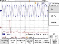
Here's an actual scope capture of the tube portion of the hybrid prototype reproducing 20 Khz at about 130Vp-p using the voltage doubler and tripler as I described in my last post. And the offset only is shifting 20mV from a zero signal condition and is also nearly insensitive to changes in supply mains voltages. This circuit has only about 6db of AC loop feedback as tested.
Attachments
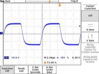
Here's the circuit's impression of a 100Khz square wave at just under 30Vp-p indicating its wide small signal bandwidth and balanced transition performance. The slight fuzz is due to test bench supply ripple what with those simple capacitor input supplies which I will change to CLC Pi filters in the actual amp. I expect the slewing characteristics to degrade somewhat when I add power mosfets to it, but hopefully not too much!
Attachments
jam said:Do you have any particular topology or design you like. Please post it here and any reasons why you care for the design. Maybe our resident guru's (Pass, Curl and Hansen) would join in and share their ideas.
My entry............
JAM
I kinda like this one. One question, why cascode the JFETs with BJTs? Why not use JFET cascodes?
- Status
- This old topic is closed. If you want to reopen this topic, contact a moderator using the "Report Post" button.
- Home
- Amplifiers
- Solid State
- Amplifier Topologies