D
Deleted member 148505
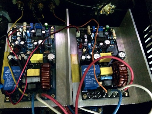
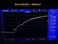
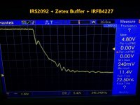
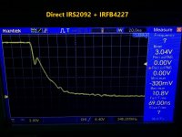
Low side gate waveforms for
1. IRS2092 with zetex 3003 driving IRFB4227 (left)
2. IRS2092 directly driving IRFB4227 (right)
Setup:
+/-53V DC rails
350khz operating frequency
Probe is in gate of lowside IRFB4227 and -V rail
Gate drive current consumption for irs2092 with zetex buffer is 3mA higher than direct irs2092.
irs2092 with zetex buffer is 6 deg celsius cooler than unbuffered irs2092 IC
Can't see advantage of buffered module aside from cooler IC.
Buffered IRS2092
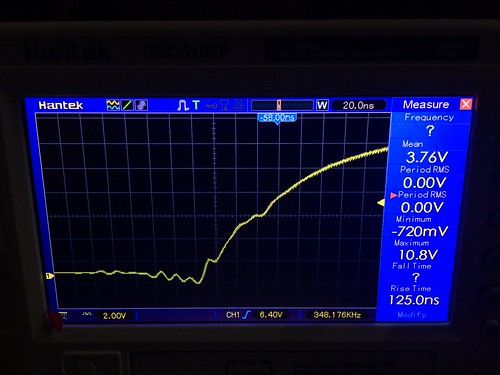
Direct IRS2092
Buffered IRS2092
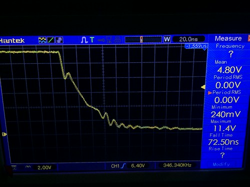
Direct IRS2092
1. IRS2092 with zetex 3003 driving IRFB4227 (left)
2. IRS2092 directly driving IRFB4227 (right)
Setup:
+/-53V DC rails
350khz operating frequency
Probe is in gate of lowside IRFB4227 and -V rail
Gate drive current consumption for irs2092 with zetex buffer is 3mA higher than direct irs2092.
irs2092 with zetex buffer is 6 deg celsius cooler than unbuffered irs2092 IC
Can't see advantage of buffered module aside from cooler IC.
Buffered IRS2092
Direct IRS2092
An externally hosted image should be here but it was not working when we last tested it.
Buffered IRS2092
Direct IRS2092
An externally hosted image should be here but it was not working when we last tested it.
Attachments
Yes, we can use IRFB4615 with DT 45ns 400khz to 600khz with this buffered IRFB4615.
Ok, can I decrease DT with PWM @ 400Khz ?
D
Deleted member 148505
Ok, can I decrease DT with PWM @ 400Khz ?
Yup we can use DT1 using OptiMOS mosfet.

Hey jLester,
Have you any experience with mounting the MOSFETs to the heatsink with an Alumina pad instead of the usual thin insulator - as a way to decrease the amount of capacitance needing to be charged by the gate drivers?
I recall Tripath used to do that on their early demo boards for the TA010x series.
BTW - love the modules I bought from you. Very nicely made. Sound good, too.
mr coffee
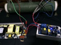
Testing the built-in bridge adapter of JLAmp1600D, paired with JLAmp1200D (identical gain).
Test setup:
Supply +/-85V DC (dropped to +/-70V @ full power)
Dummy Load: 8 ohms resistive (4 ohms test to follow)
Result:
88V RMS (below clipping)
968W @8ohms
Thick part of sinewave is the carrier frequency (330khz)
im nearly ready to order some boards from you but i keep seeing interesting things, could you elaborate on the JLamp1600? please, what is the max rail voltage and 8ohm output? and when is the jla1000 going to be listed? Greg
D
Deleted member 148505
IPD530N15N3, very good spec.Which model ?
Haven't tried it yet, does it have large improvement on capacitance reduction to justify the cost? Thank you again!Hey jLester,
Have you any experience with mounting the MOSFETs to the heatsink with an Alumina pad instead of the usual thin insulator - as a way to decrease the amount of capacitance needing to be charged by the gate drivers?
I recall Tripath used to do that on their early demo boards for the TA010x series.
BTW - love the modules I bought from you. Very nicely made. Sound good, too.
mr coffee
im nearly ready to order some boards from you but i keep seeing interesting things, could you elaborate on the JLamp1600? please, what is the max rail voltage and 8ohm output? and when is the jla1000 going to be listed? Greg
JLAmp1600D is only a prototype and was never released, Also, I won't be selling class-d modules with greater than 85V DC rails. For the JLA1000D, ZXGD3003E6 is very difficult to solder by ordinary tool. Not good for DIYers. I will be replacing it with larger, (probably through hole) buffer.
D
Deleted member 148505
It possible to use PWM @ +500Khz @ DT1 25ns with Infineon IPD530N15N3 and Zetex buffer on the JLA1000D ?
Yes but rail voltage should be up to +/- 50V DC only, heatsinking should be good.
D
Deleted member 148505
D
Deleted member 148505
Difference is added low pass filter in feedback section, weeds out high frequency spectrum to avoid TIM distortion in the error amplifier. Also has external VAA/VSS supply for better efficiency (and better sound according to some). Added buffered gate drive.
For high power version (+/- 70V to 80V): I use IRFB4127 + 1D31A inductor.
For low power "audiophile" (+/- 45V to 55V): IPD530N15N3 + VER2923-223KL
JLE-1500D width is smaller 2.6 inch, but length is longer 6.5 inch.
Both don't have an onboard preamp or input buffer for unadulterated sound.
For high power version (+/- 70V to 80V): I use IRFB4127 + 1D31A inductor.
For low power "audiophile" (+/- 45V to 55V): IPD530N15N3 + VER2923-223KL
JLE-1500D width is smaller 2.6 inch, but length is longer 6.5 inch.
Both don't have an onboard preamp or input buffer for unadulterated sound.
D
Deleted member 148505
D
Deleted member 148505
Hi Lester does your speaker protector have a power on delay? Thanks Greg
Yes, power on delay is included
D
Deleted member 148505
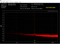
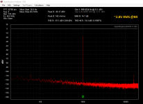
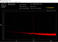
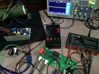
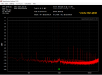
Some quick THD spectrum measurements for JLE-800D.
Here are the setup.
JLE-800D
Gain: 36
Deadtime: DT3
Speaker protect is powered by battery (reason: i don't have other power supply)
Power Supply: +/-53V abletec SMPS
JLE Interface setup
Power supply: 7812/7912 12-0-12 transformer mains supply 220VAC (reason: i don't have extra batteries)
Ground of qa400 and DUT is connected
DIV10 switch is turned on, THAT1206 is used so additional -6db attenuation.
For 28.8V RMS @8R measurement, baxandall active volume control is used to attenuate signal to 537mvrms. (28.8 DIV10 = 2.88 then reduced further)
Oscilloscope is turned on and laptop power supply is connected.
Just ignore 16khz hash, it is not there when only JLE interface is connected.
I'll make cleaner measurements soon when I acquire good cables and battery for the JLE Interface.
Attachments
- Status
- Not open for further replies.
- Home
- Vendor's Bazaar
- Amplifier Modules and PCBs For Sale