D
Deleted member 148505
Hi Lester, Its been a slow build due to waiting for parts to arrive, anyway i had no problems with either board both sound really nice and detailed and not bright or harsh, credit to you for a quality design. my rails are +-60v and im getting about 130w at 8r with a 100hz sine wave at just below clipping. Greg
Linear power supplies usually have a voltage drop of 7 to 8VDC for 8 ohms, 13 to 15VDC for 4 ohms and 16 to 18VDC at 2 ohms near clipping.
If you try it with SMPS regulated supply (very stiff) you'll achieve rated wattage.
-------
Also I have received reports that in some conditions, the zobel resistor overheats.
This usually happens when load (speaker) is not connected and there is dangling input wire that is also not connected at the source. It makes the output filter resonate, the zobel resistor is not rated to handle that scenario.
I was able to reproduce the scenario in stereo mode (2 modules running). When it happens, 2 modules are eating around 25W more power than idle (measured in AC outlet wattmeter).
For setups where the speaker is permanently connected, there will be no problem. But for full range output setups where it might happen, I suggest to move the zobel resistor + capacitor to the speaker terminal inside the chassis. Use 10W rated chassis mounted resistor. (I was able to measure the current on zobel resistor at worse scenario, it will generate 3W, so 10W is safe.)
Thanks,
Lester
D
Deleted member 148505
Good to see that Jan !
I think your "quality made" module associate to the pre-filter schema of chocoholic can make a magic result .
I read the post of the SystemD LiteAmp, impress by the result without "quality components" @ 10W/4R: -91.1 dB / 0.0028% THD
Comparing to your measurement of the JLA250/800 it is the same (normally at 8R => less THD than 4R), but it's just measurement, can't replace serious listening !
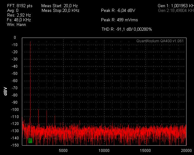
It is expected to have lower THD because of post filter feedback topology and it has lower deadtime setting (25ns), mine has 75ns setting.
As for the noise, JLE-250D and 800D have normal gain setting of about 36x of input (IRAUDAMP7 standard). Also when I measured my amps I am not using RC filter box or AES-17, though my interface has a first order lowpass filter with 400khz cutoff freq. I'll check next time if (further) filtering the carrier will improve the measurements.
Linear power supplies usually have a voltage drop of 7 to 8VDC for 8 ohms, 13 to 15VDC for 4 ohms and 16 to 18VDC at 2 ohms near clipping.
If you try it with SMPS regulated supply (very stiff) you'll achieve rated wattage.
-------
Also I have received reports that in some conditions, the zobel resistor overheats.
This usually happens when load (speaker) is not connected and there is dangling input wire that is also not connected at the source. It makes the output filter resonate, the zobel resistor is not rated to handle that scenario.
I was able to reproduce the scenario in stereo mode (2 modules running). When it happens, 2 modules are eating around 25W more power than idle (measured in AC outlet wattmeter).
For setups where the speaker is permanently connected, there will be no problem. But for full range output setups where it might happen, I suggest to move the zobel resistor + capacitor to the speaker terminal inside the chassis. Use 10W rated chassis mounted resistor. (I was able to measure the current on zobel resistor at worse scenario, it will generate 3W, so 10W is safe.)
Thanks,
Lester
Hi, my power supply is a smps, and i did measure rail voltage at clipping and there was no sag. what areas should i look at to work out what going on? i was expecting 150w or slightly more at 60v rails. i was very impressed with the sound quality though. thanks Greg
photos to follow
I double checked my smps and connected another irs2092 class d board i have and managed 38vrms into 8r vs the best i could get from the jle800 was 34vrms just below clipping. one thing i noticed was the carrier signal of the jle800. at idle with input grounded and 8r dummy load i had 3.5vpp carrier on the output. my other amp had only 1vpp. Would the output filter need adjusting to suit the lower frequency of the 4227 build?
thanks Greg
thanks Greg
D
Deleted member 148505
Hi, my power supply is a smps, and i did measure rail voltage at clipping and there was no sag. what areas should i look at to work out what going on? i was expecting 150w or slightly more at 60v rails. i was very impressed with the sound quality though. thanks Greg
photos to follow
Is the load you're using resistive? You should use high power resistor (not speaker) so that the resistance is not changing at different test frequencies, also when the resistor heats up, the resistance slightly changes so you should measure it too.
Also check if your multimeter RMS reading is changing depending on frequency used. Usually they are accurate at 60hz.
The sine wave generator - output voltage steps should also be smooth,... maybe the step between clipping and below clipping is big, putting it in-between is hard (like in stepped attenuator)
Stiff +/-60V DC rails should produce clean 160W below clipping. And 220W at visible clipping.
If you have wattmeter, you will see the whole power consumption of the system at specific output power. For SMPS + class-d combo, usual efficiency at full power is around 80% to 85% so you will have a picture of the actual output power.
D
Deleted member 148505
I double checked my smps and connected another irs2092 class d board i have and managed 38vrms into 8r vs the best i could get from the jle800 was 34vrms just below clipping. one thing i noticed was the carrier signal of the jle800. at idle with input grounded and 8r dummy load i had 3.5vpp carrier on the output. my other amp had only 1vpp. Would the output filter need adjusting to suit the lower frequency of the 4227 build?
thanks Greg
What is the carrier frequency of your other class-d? Did you assemble the IRFB4227 build? Can you adjust the carrier frequency higher? When the carrier frequency is low, the carrier residual will be higher because the output filtering is better at higher frequencies (designed for 400khz).
Also when you are measuring output power, find the "averaging" menu on your oscilloscope to see the real signal, because you might mistaken the carrier residual at the peaks of the sinewave as "clipping point"
Regards,
Lester
My other amp is magazine kit called a classic d from silicon chip mag, its frequency is 500khz. my scope is an old analogue 20meg crt unit, there is no averaging feature. clipping is clearly visible though, i will post up some pictures of my test setup tomorrow night. thanks Greg
D
Deleted member 148505
D
Deleted member 148505
Hi Greg, I received your email, can you repeat and compare your measurements with matched carrier residual amplitude with the other amp?
Because I think your multimeter is not including the carrier that is riding in the output signal in its measurements.
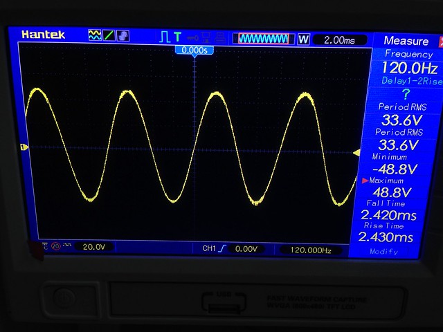
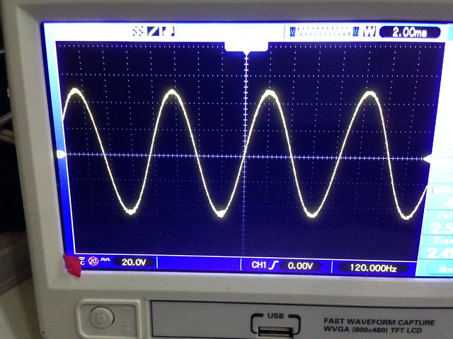
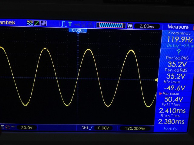
Example is your picture below. The clipping point is already touching the rails (oscilloscope setting is 20V/div), power supply is +/- 60V DC.
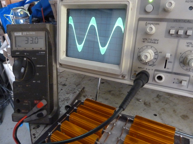
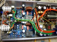
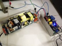
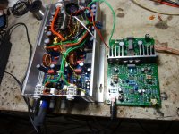
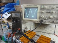
Here is my test setup similar to yours' except that I'm using abletec SMPS +/- 53.5VDC rails. 8 ohms resistive dummy load. IRB4227 300khz carrier frequency.
Picture below is actual, non averaged signal.
Carrier residual that is riding on the output signal is thick.
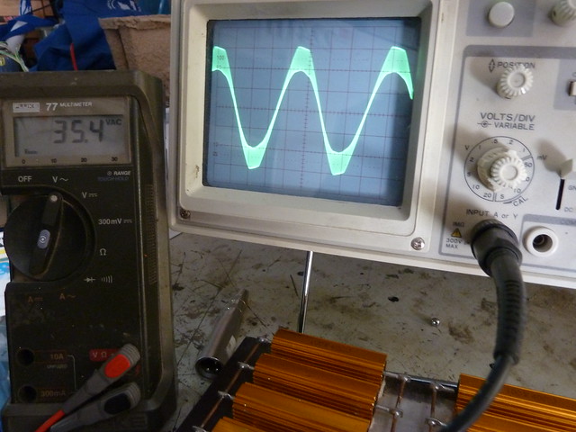
When averaging is enabled on the oscilloscope here is the same averaged output signal. (the carrier residual was ignored)
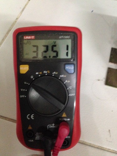
Here is the reading on my multimeter.
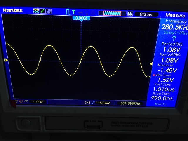
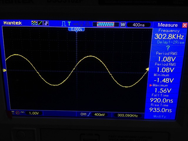
Here is the carrier residual amplitude at 280khz. 1VRMS = 2.8Vpp
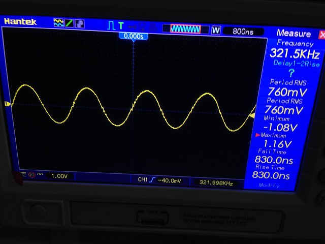
Carrier residual amplitude at 320khz. Reduced to 760mVrms
Carrier residual with my linear power supply +/-55V DC same module. blip is very small
Since your IC has a heatsink, I think you can safely increase the self osc frequency to 360kHz, so that carrier residual will be lowered without changing the output filter values.

If you used the recommended IPP320N20N3, you can increase it to 550khz without problems. (disadvantage is the slightly hotter inductor)
Thanks and regards,
Lester
Because I think your multimeter is not including the carrier that is riding in the output signal in its measurements.
Example is your picture below. The clipping point is already touching the rails (oscilloscope setting is 20V/div), power supply is +/- 60V DC.
Here is my test setup similar to yours' except that I'm using abletec SMPS +/- 53.5VDC rails. 8 ohms resistive dummy load. IRB4227 300khz carrier frequency.
Picture below is actual, non averaged signal.
Carrier residual that is riding on the output signal is thick.
When averaging is enabled on the oscilloscope here is the same averaged output signal. (the carrier residual was ignored)
Here is the reading on my multimeter.
Here is the carrier residual amplitude at 280khz. 1VRMS = 2.8Vpp
Carrier residual amplitude at 320khz. Reduced to 760mVrms
Carrier residual with my linear power supply +/-55V DC same module. blip is very small
Since your IC has a heatsink, I think you can safely increase the self osc frequency to 360kHz, so that carrier residual will be lowered without changing the output filter values.
If you used the recommended IPP320N20N3, you can increase it to 550khz without problems. (disadvantage is the slightly hotter inductor)
Thanks and regards,
Lester
Attachments
Last edited by a moderator:
D
Deleted member 148505
Thanks for taking the time to post all this great info, much appreciated. hopefully I've attached the photos of my same test of my other class d board the silicon chip magazine "classic d" board. irs2092s 500khz irfb5615. as requested. thanks Greg
Attachments
D
Deleted member 148505
You're welcome, carrier residual is almost the same with the one I posted above.
When the residual is not fully filtered, it adds on top of the sinewave which make the whole signal appear as clipping. Meaning the audio signal is not yet clipping, but the residual is.
What's important is that the audioband signal clips almost rail to rail.
Regards,
Lester
When the residual is not fully filtered, it adds on top of the sinewave which make the whole signal appear as clipping. Meaning the audio signal is not yet clipping, but the residual is.
What's important is that the audioband signal clips almost rail to rail.
Regards,
Lester
Last edited by a moderator:
D
Deleted member 148505
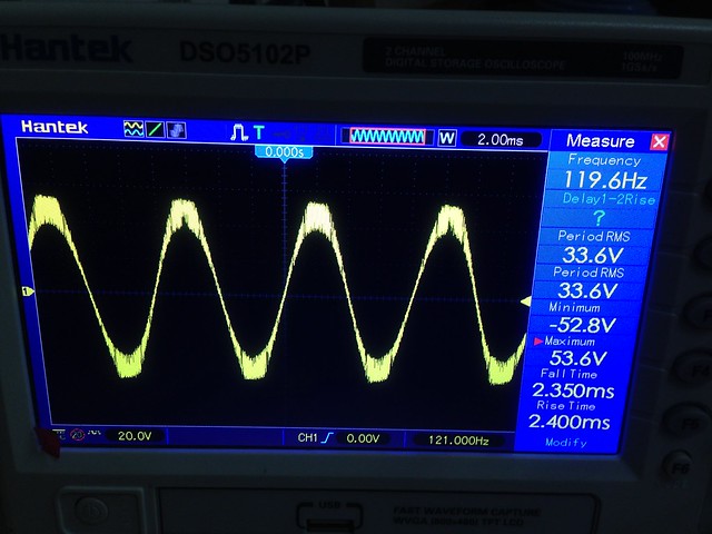
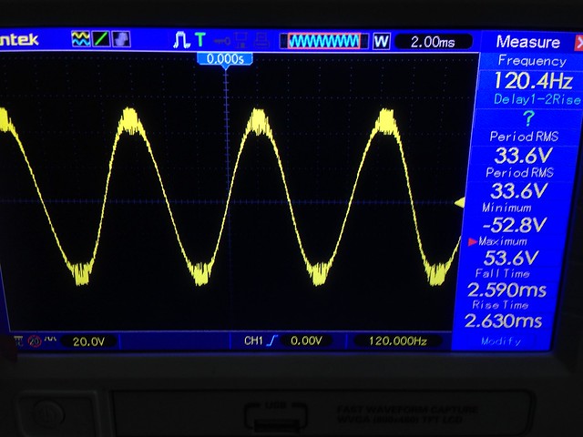
Here is a module set at 300kHz. It appears that the signal is clipping.
(because the residual on top of 120hz cannot get higher than the rails)
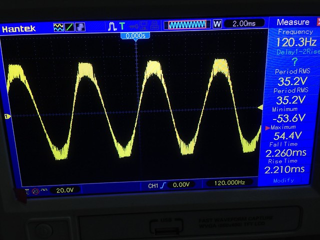
But when same signal is averaged (or if carrier is filtered). The 120hz original output is actually not yet clipping.
This is abletec's +/-54V (actual +/-53.5V) and i'm getting 155W below clipping at 8R.
(because the residual on top of 120hz cannot get higher than the rails)
But when same signal is averaged (or if carrier is filtered). The 120hz original output is actually not yet clipping.
This is abletec's +/-54V (actual +/-53.5V) and i'm getting 155W below clipping at 8R.
Last edited by a moderator:
D
Deleted member 148505
D
Deleted member 148505
Updated products for 2017
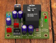
Softstart (PCB size 2.5" x 2.85")
- Resistors are removed, and should be mounted on chassis so that you can use large resistors like 50W
- PCB mounted transformer
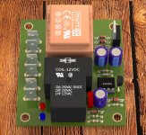
Speaker protect (PCB size 2" x 2.6")
- just smaller
Softstart (PCB size 2.5" x 2.85")
- Resistors are removed, and should be mounted on chassis so that you can use large resistors like 50W
- PCB mounted transformer
Speaker protect (PCB size 2" x 2.6")
- just smaller
Attachments
D
Deleted member 148505
D
Deleted member 148505
Cool Lester !
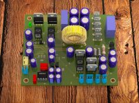
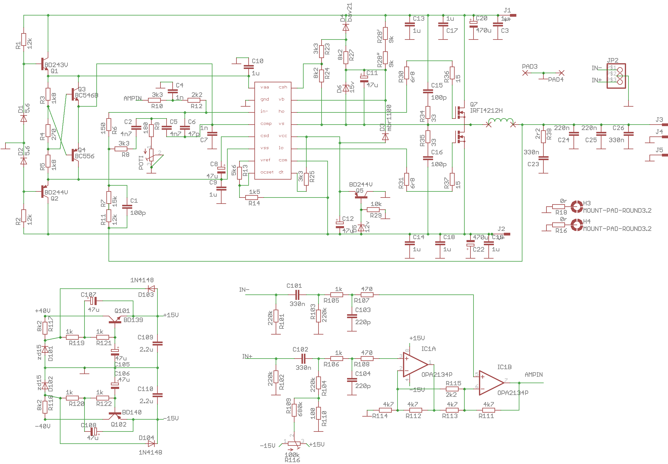
This is the Chocolic SystemD schematic :
Yup, almost the same except that my prototype has gate drive buffers so that it can be partnered with any mosfets. The front end I used is single ended. I have a separate balanced receiver board which uses THAT1206 that I will partner with it.
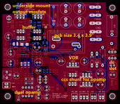
Like all my class-d boards the heatsink is L-type mounting so that it can be attached to a larger heatsink. Mosfets are attached on the underside of the board. PCB is only 3.4" x 3.9" so 4 x 4 inch L bar heatsink will fit which is common in my place hehe.
My prototype also has a different power supply requirements. It needs +/- 15V to 24V external supply for the opamp. Then +15V to 24V external VDR supply referenced to -V. It also has a DC detect with an open collector output similar to nFatal pin of NC400. So SMPS600 or similar SMPS will be compatible to it.
On my listening tests I found the JLE-2000D much more fuller and livelier, more natural sounding amp compared to my JLE-800D or JLA-250D which uses easier to drive 1 pair of mosfets. JLE-2000D has a higher measured THD, more than triple in numbers than the 800D so I'm not that too excited with the PFFB version which has lower THD... maybe it will sound more analytical, but let's see
Attachments
- Status
- Not open for further replies.
- Home
- Vendor's Bazaar
- Amplifier Modules and PCBs For Sale