D
Deleted member 148505
Ok I see your modification, th AOP in the pre-stage filter is a single or double ?
It's possible to connect the input in "AMP IN" pin directly after the pre-stage filter ?
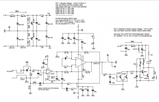
For the front end, I used dual opamp (like ne5532, lm4562, lme49720). First opamp is a voltage follower, the second one is inverting opamp with gain. So the whole module becomes a non inverting amp. LiteAmp has a low gain to further reduce the noise of the OTA. So if you will bypass the front end, you need to drive the liteamp with a 6Vrms signal.
To bypass the frontend, you need to remove the opamp and tap the appropriate pins.
Ok it is better to use the input of the pre-stage then ... 6V RMS it's not possible directly after the DAC in asymetrical (2V max).
I wait more listening comparaison VS the JLA-250/800 when your have finalized the JLA-2000, measurement to support the comparison it's appreciable !
The presence of the AOP in the pre-stage filter doesn't lose details in the music ?
I wait more listening comparaison VS the JLA-250/800 when your have finalized the JLA-2000, measurement to support the comparison it's appreciable !
The presence of the AOP in the pre-stage filter doesn't lose details in the music ?
D
Deleted member 148505
What is AOP? You can increase the gain of the OTA so that it can accept 2Vrms. At the expense of higher noise floor.
Yup i'll make THD measurement comparisons after I created the liteamp.
AOP = operationnal amplifier ... sorry French deformation
D
Deleted member 148505
The presence of the AOP in the pre-stage filter doesn't lose details in the music ?
THD of the front end is lower than my measuring equipment (qa400) when it is measured independently. We'll see if how it will affect the sound...
AOP = operationnal amplifier ... sorry French deformation
ok got it
")
update on jle800
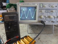
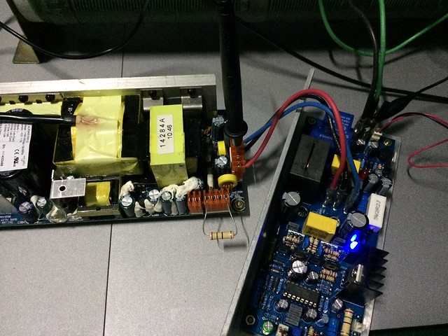
Hi Leister, i have finally received the polypropylene output filter caps and changed the feedback resistor and capacitor to 1k and 100pf the oscillation frequency is around 350khz now. the output carrier has now dropped to just under 1vpp. my measured output power is now showing nearly 180w just before clipping. and the sound quality is very nice. overall im very pleased with the performance, size and quality. thank you Greg
Hi Leister, i have finally received the polypropylene output filter caps and changed the feedback resistor and capacitor to 1k and 100pf the oscillation frequency is around 350khz now. the output carrier has now dropped to just under 1vpp. my measured output power is now showing nearly 180w just before clipping. and the sound quality is very nice. overall im very pleased with the performance, size and quality. thank you Greg
Attachments
D
Deleted member 148505
D
Deleted member 148505
PCBs have arrived, some will be released on 2017
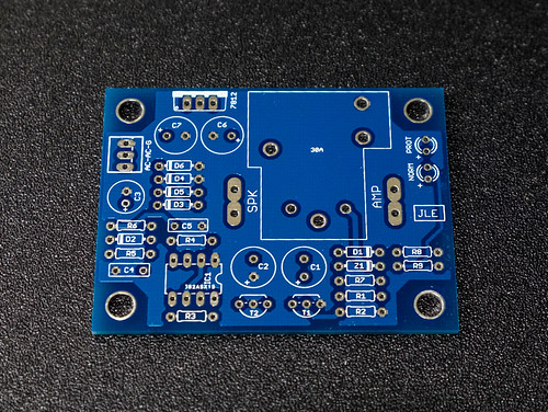
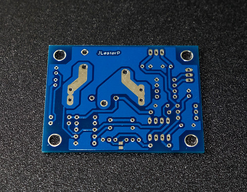
Speaker protect 2" x 2.6"
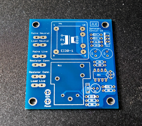
Softstart / Power on delay circuit, pcb mount transformer, no resistor onboard 2.5" x 2.85"
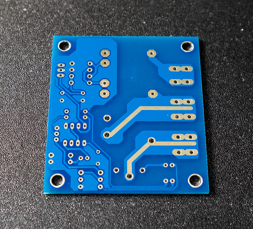
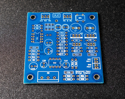
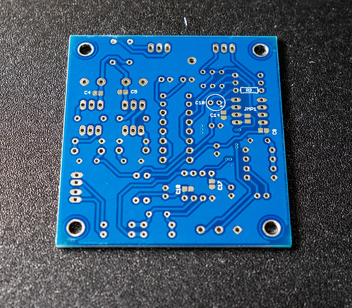
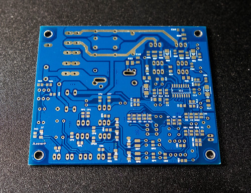
Bridging Adapter with balanced receiver (compatible with THAT1200 / INA134 through optional parts) 2.5" x 2.6"
LM3886 based on Myref (designed for SMPS use) 2.1" x 5"
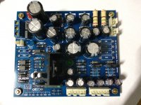
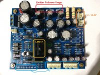
Housekeeping supplies take much of the class-d PCB space so I created a supply using linear regulators. It can provide opamp and gate driver supply, it's capable of powering 2 modules with heavy duty gate drivers, as well as trigger for OVP, UVP. Also provided enable trigger (optocoupler open collector). (not for sale) 3.3" x 3.9"
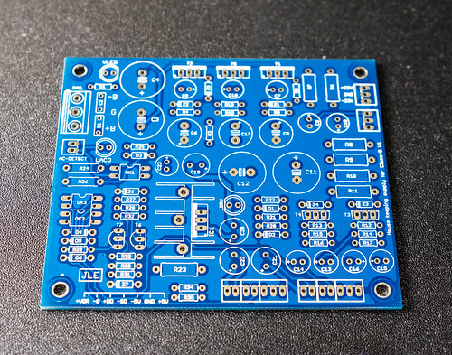
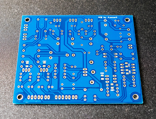
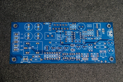
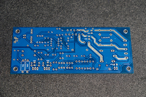
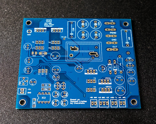
Based on LiteAmp by chocoholic (not for sale) 3.4" x 3.9"
Speaker protect 2" x 2.6"
Softstart / Power on delay circuit, pcb mount transformer, no resistor onboard 2.5" x 2.85"
Bridging Adapter with balanced receiver (compatible with THAT1200 / INA134 through optional parts) 2.5" x 2.6"
LM3886 based on Myref (designed for SMPS use) 2.1" x 5"
Housekeeping supplies take much of the class-d PCB space so I created a supply using linear regulators. It can provide opamp and gate driver supply, it's capable of powering 2 modules with heavy duty gate drivers, as well as trigger for OVP, UVP. Also provided enable trigger (optocoupler open collector). (not for sale) 3.3" x 3.9"
Based on LiteAmp by chocoholic (not for sale) 3.4" x 3.9"
D
Deleted member 148505
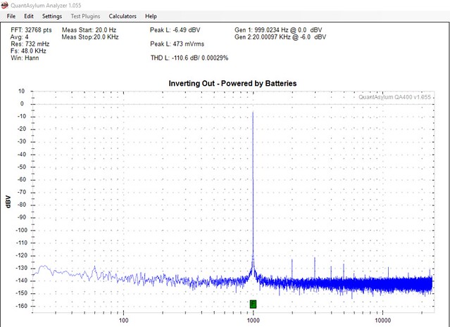
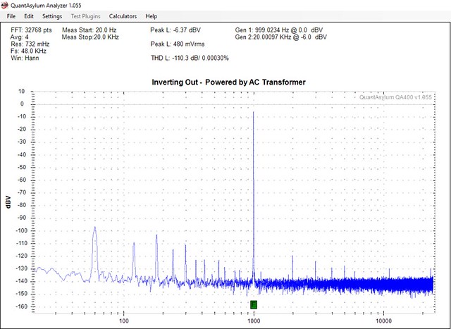
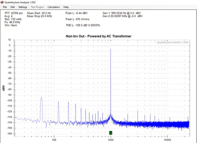
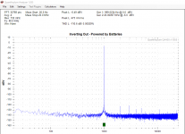
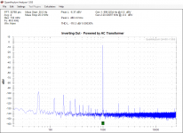
I tested my bridge adapter module using THAT 1256P08-U for balanced receiver IC and LME49720 for bridge output.
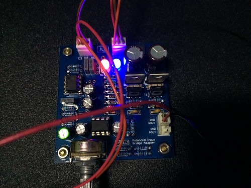
THD measurements (single ended input only from QA400 to hot and cold pins of THAT1256)
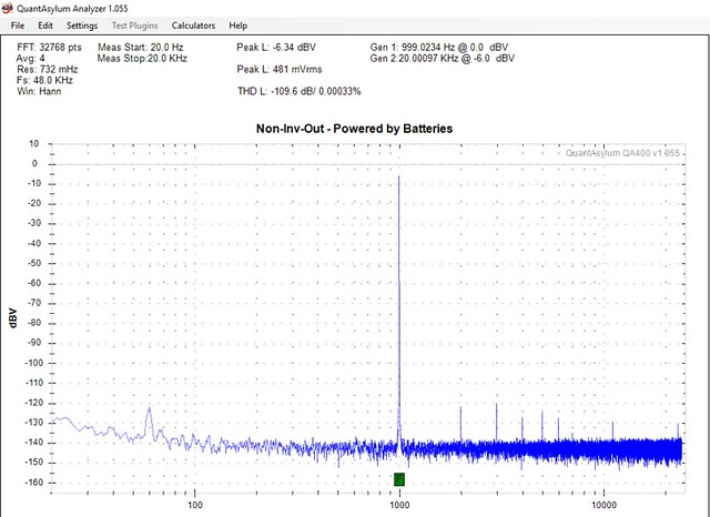
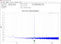
Using battery for power supply.
Inverting output
Non Inverting output
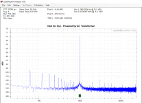
Using 12-0-12V AC transformer for power supply
Inverting output
Non Inverting output
THD measurements (single ended input only from QA400 to hot and cold pins of THAT1256)
Using battery for power supply.
Inverting output
Non Inverting output
Using 12-0-12V AC transformer for power supply
Inverting output
Non Inverting output
Attachments
Last edited by a moderator:
Hi JLester,
Do you have the BOM for your Auto Power-On Signal Detect posted anywhere? I thought I had it in my email but I can't seem to find it. I'd like to get mine working next week.
Thanks,
No worries. I found it in my email
D
Deleted member 148505
D
Deleted member 148505
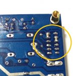
For those who are experiencing early triggering of relay for JLA-250D boards (and derivatives) solder 100nf 0805 SMD directly on the base-emitter pins of T1 and T2 (DC detect portion). Only some 2n5551's are affected and are too sensitive.
Attachments
D
Deleted member 148505
D
Deleted member 148505
D
Deleted member 148505
Whoau, how many supply is integrated on the board ?
What is the regulators you use ?
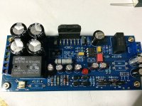
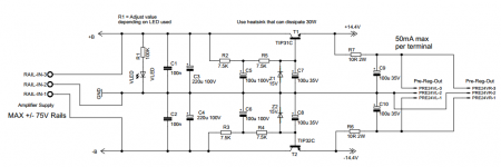
The module accepts dual supply like +/- 75VDC, there are transistor series voltage regulators for generating +/- 14.4V, and +24V referenced to -B (for class-d driver supply)
+/- 14.4V supplies (orange box) are tapped for class-d aux supplies. (+/- 50mA MAX per terminal)
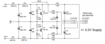
+/- 14.4V is regulated by transistor shunt vreg for generating 5.3V (+/- 15mA MAX each per terminal for powering IRS2092 VAA/VSS supplies)
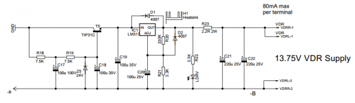
+24V is regulated by LM317 for class-d driver supply. (80mA MAX per terminal)
The SD pins are controlled by PC817 optocouplers activated by undervoltage, overvoltage and loss of AC detect (12vac input) 3pcs PC817.
Since it's linear reg, disadvantage is that it has ridiculously high dissipation. It's better not to consume lots of current on +/- 14.4V pre-regulator output.
Attachments
Last edited by a moderator:
D
Deleted member 148505
Yes very good lester !
If I understood correctly it provided all the tensions from the main one, no need for other auxilliary power ?
How many LiteAmp module he can supply ?
Hi Alex,
It can power 2 modules, though It's not designed for my prototype liteamp.
My prototype liteamp's opamp section has shunt current of 45mA per rail, so it is not suitable with my linear housekeeping supply module.
Because for example, with 65V DC rails, the housekeeping supply will dissipate continuous 9.1W for the 2 module's opamp section and 4.1W for the 2 module's gate driver supply's 80mA current draw. Dissipation will increase on higher rails. Total of around 20W dissipation for 1 housekeeping supply + 2 liteamp modules. For system power consumption, add another losses for main power supply section . That will somewhat defeat the purpose of (eco-friendly) class-d in home listening
I designed my prototype liteamp to be used with SMPS's with built-in +/-15V and 15V VDR supplies. It will be very efficient when used with independent aux supplies. Almost no heat on idle.
D
Deleted member 148505
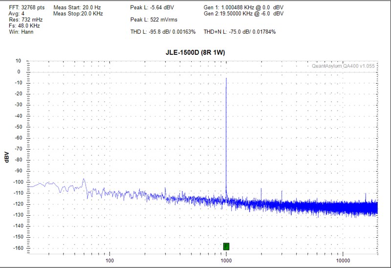
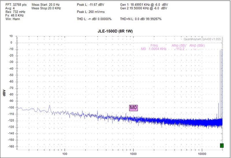
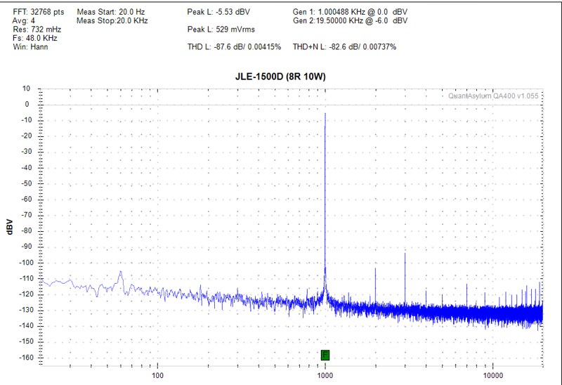
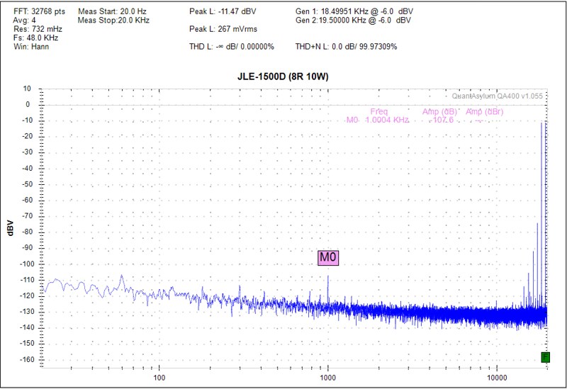
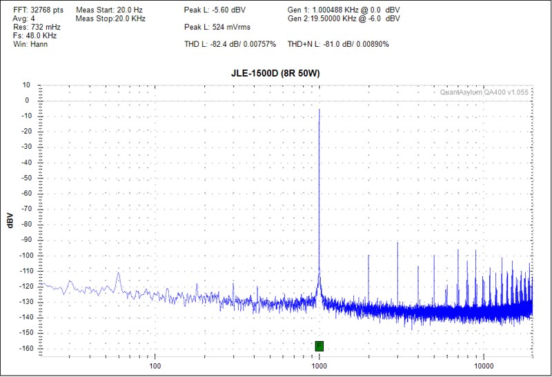
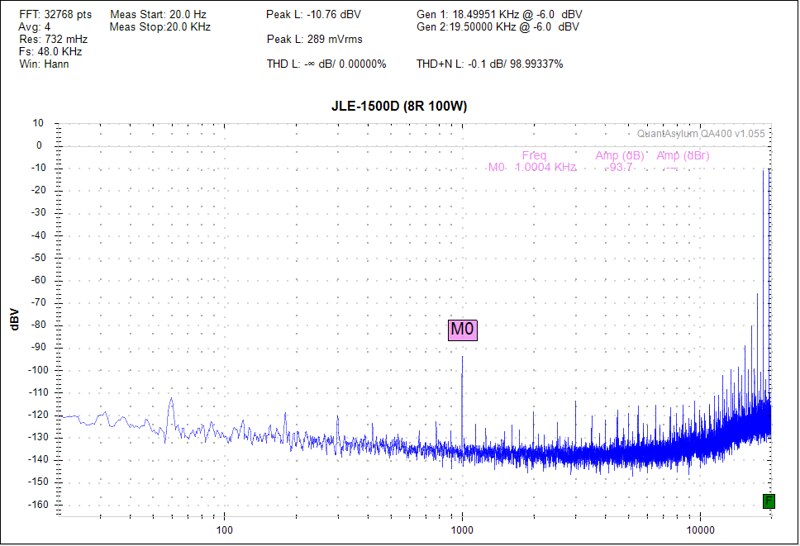
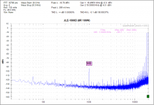
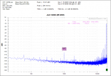
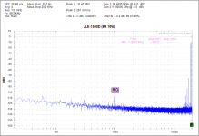
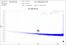
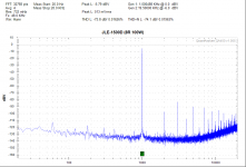
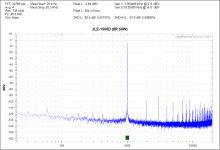
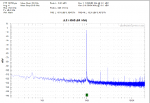
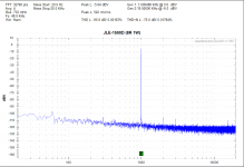
JLE-1500D THD+IMD measurements 8R load. 1W, 10W, 50W, 100W. All are referenced to -6dbV. No AES-17 nor RC box filter used.
Output mosfets: IRFB4227
IRS2092 deadtime setting: DT4


Output mosfets: IRFB4227
IRS2092 deadtime setting: DT4
Attachments
-
 8R 100W IMD.PNG44.7 KB · Views: 50
 -
 8R 50W IMD.PNG43.1 KB · Views: 39
 -
 8R 10W IMD.PNG40.8 KB · Views: 36
 -
 8R 1W IMD.PNG39.2 KB · Views: 34
 -
 8R 100W.PNG42.5 KB · Views: 44
 -
 8R 50W.PNG42.8 KB · Views: 31
 -
 8R 10W.PNG39.4 KB · Views: 35
 -
 8R 1W.PNG38.2 KB · Views: 36
 -
 31562415300_62cf3896d4_z.jpg113.3 KB · Views: 64
Last edited by a moderator:
- Status
- Not open for further replies.
- Home
- Vendor's Bazaar
- Amplifier Modules and PCBs For Sale