D
Deleted member 148505
In your ears leaster what sounds the best? Your 250D or GB150D?
Depends on your taste, if you want detailed, "airy" sound and captures the whole soundstage, go for JLAudiophile-250D.
If you want smooth and mellow sound, go for GB150D.
D
Deleted member 148505
Very nice work, Lester. Will you be selling the assembled and tested module any time soon?
Yes, still sourcing parts for mass prod.
An externally hosted image should be here but it was not working when we last tested it.
An externally hosted image should be here but it was not working when we last tested it.
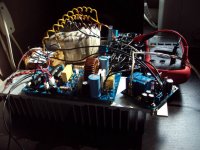
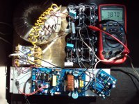
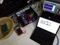
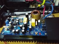
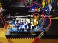
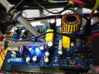
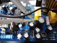
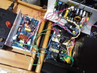
Finally assembled JLAmp1200D with safe +-78VDC power supply. Everything works great. Only have to be careful with gain, it really have A LOT of power.
Best Regards Everyone
http://ifotos.pl/z/wwehnxh
http://ifotos.pl/z/wwehnnh
D
Deleted member 148505
Finally assembled JLAmp1200D with safe +-78VDC power supply. Everything works great. Only have to be careful with gain, it really have A LOT of power.
Best Regards Everyone
ifotos.pl - najlepszy darmowy hosting zdj?? i obrazków!
ifotos.pl - najlepszy darmowy hosting zdj?? i obrazków!
Thank you for choosing jlamp1200d for your subwoofer
") Don't hesitate to message me if you need help.
Don't hesitate to message me if you need help.Attachments
D
Deleted member 148505
D
Deleted member 148505
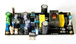
JLAudiophile-900D
IRAUDAMP7 based class-d with totem pole buffer for high oscillation frequency (~700kHz), ~50ns deadtime setting. More analogue sound.
Uses IRFB4615 and VER2923-223 inductor for higher current capability.
-----------------------------------------------------
Can also be configured for 900W version using 1pair IRFB4127 and T157-2 inductor and some resistor values adjustment.
Attachments
D
Deleted member 148505
Power measurements for JLAmp1200D
2 pairs IRFB4127, T157-2 18uH inductor
+/-84VDC Rail supply
270kHz idle oscillating frequency
-------------------------------------------
Output Power Results
120hz 54V RMS at 8 ohms
364.5W at 8 ohms
84V dropped to 79VDC
120hz 52V RMS at 4 ohms
676W at 4 ohms
84VDC dropped to 73VDC
120hz 48V rms at 2 ohms
1152W at 2 ohms
84VDC dropped to 65VDC
Power measurement is only done in 10 seconds, will upload FTC power measurements using 1/3 rated power in 15 minutes on youtube.
Attachments
D
Deleted member 148505
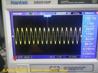
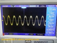
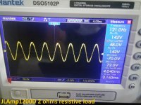
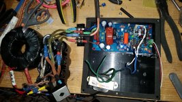
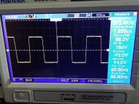
Some measurements for JLAudiophile-900D
1pair IRFB4615, Ver2923-153 inductor
Credits to my friend Efren (from cebu) for doing the measurements
Test conditions
+/-65VDC Rail voltage
700kHz oscillating frequency
1khz sinewave input.
Results:
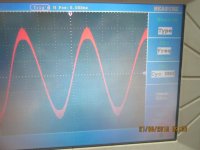
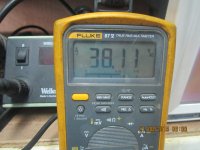
38.11VAC at 8 ohms load
181W at 8ohms load
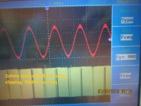
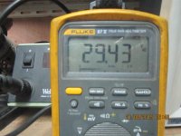
29.43VAC at 2 ohms load
433W at 2 ohms load
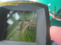
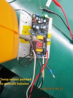
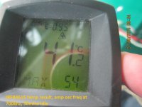
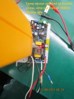
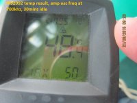
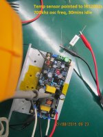
Temp measurements, amp is idle for 30mins 700khz osc freq.
IRS2092 = 48deg C
IRFB4615 = 41deg C
Inductor = 37deg C
LM350 = 42deg C
Heatsink = 32deg C
1pair IRFB4615, Ver2923-153 inductor
Credits to my friend Efren (from cebu) for doing the measurements
Test conditions
+/-65VDC Rail voltage
700kHz oscillating frequency
1khz sinewave input.
Results:
38.11VAC at 8 ohms load
181W at 8ohms load
29.43VAC at 2 ohms load
433W at 2 ohms load
Temp measurements, amp is idle for 30mins 700khz osc freq.
IRS2092 = 48deg C
IRFB4615 = 41deg C
Inductor = 37deg C
LM350 = 42deg C
Heatsink = 32deg C
Attachments
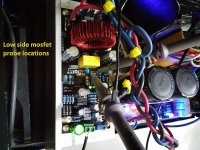
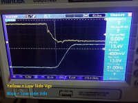
-
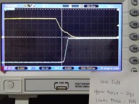
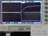
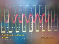 prefilter postfilter waveform at 700khz.jpg264.3 KB · Views: 65
 -
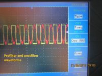 prefilter and postfilter waveform.jpg252.3 KB · Views: 58
 -
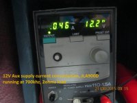 aux current consumption.jpg218.7 KB · Views: 54
 -
 output waveform 29.43vac at 2ohms resistive.jpg259.9 KB · Views: 62
 -
 RMS output at 2ohms.jpg375.5 KB · Views: 56
 -
 8ohms load output waveform.jpg380 KB · Views: 60
 -
 RMS output at 8ohms.jpg371.5 KB · Views: 79
D
Deleted member 148505
Temp measurements, amp is idle for 30mins 700khz osc freq.
IRS2092 = 48deg C
IRFB4615 = 41deg C
Inductor = 37deg C
LM350 = 42deg C
Heatsink = 32deg C
IRS2092 = 48deg C
IRFB4615 = 41deg C
Inductor = 37deg C
LM350 = 42deg C
Heatsink = 32deg C
Attachments
-
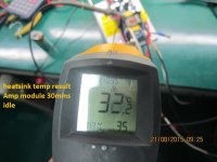 heatsink temp result.jpg206.3 KB · Views: 50
 -
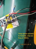 heatsink temp no cooling fan.jpg259.3 KB · Views: 50
 -
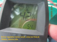 result temp read driver regulator.jpg244.3 KB · Views: 60
 -
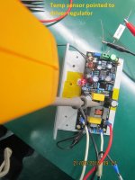 temp read driver regulator.jpg236.9 KB · Views: 48
 -
 result coilcraft temp reading 30mins 700khz.jpg241.1 KB · Views: 53
 -
 coilcraft temp reading 30mins 700khz.jpg240.4 KB · Views: 52
 -
 result temp read irfb4615 30mins 700khz.jpg262.9 KB · Views: 50
 -
 temp read irfb4615 30mins 700khz.jpg229.1 KB · Views: 49
 -
 result temp read irs2092 700khz 30mins.jpg232.3 KB · Views: 68
 -
 temp read irs2092 700khz 30mins.jpg254.7 KB · Views: 81

D
Deleted member 148505
Dancal6 inspired me to get mine built. Running at +/-84v... Only tested on an 8" woofer, free air so far but looks promising
Thanks for posting your setup, I thought you didn't build the module because you haven't contacted me for help. Anyways nice build
I updated BOM and buildguide for JLAmp1200D V1.1
Build Guide <click here>
BOM <click here>
Attachments
D
Deleted member 148505
JLAudiophile-900D running on single supply.
JLAudiophile-900D running on single supply.
Test conditions:
First video: <click here> clipping performance 1khz output 8ohms load with single supply.
Second video: <click here> sound check, PSU ground still disconnected
Didn't encounter problems probably because:
Input source is floating and is not referenced to -B.
Input signal is 1khz, according to AN-1164 Effect of floating ground fluctuation will be pronounced under low frequency signal.
Sound is crystal clear and no audible distortion probably because of very good power supply. (Load ground fluctuation is minimal)
----------------------
Note: Do not replicate!, this test only shows that single supply operation as described on AN-1164 is doable
JLAudiophile-900D running on single supply.
Test conditions:
- +/-65VDV rail supply, Power supply no protective earth ground
- VCC IRS2092 driver supply is floating
- Module ground disconnected from power supply. Only + and - terminals are connected.
- Input source is floating, and no protective earth ground (ground of input source and PSU are infinite resistance)
First video: <click here> clipping performance 1khz output 8ohms load with single supply.
Second video: <click here> sound check, PSU ground still disconnected
Didn't encounter problems probably because:
Input source is floating and is not referenced to -B.
Input signal is 1khz, according to AN-1164 Effect of floating ground fluctuation will be pronounced under low frequency signal.
Sound is crystal clear and no audible distortion probably because of very good power supply. (Load ground fluctuation is minimal)
----------------------
Note: Do not replicate!, this test only shows that single supply operation as described on AN-1164 is doable
D
Deleted member 148505
D
Deleted member 148505
JLAudiophile-250D with IRFB4227
Output mosfets directly driven by IRS2092
+/-84V DC Rails supply
330khz oscillating frequency
Output results (120hz input) (RMS)
8 ohms 380W output (10 secs)
4 ohms 650W output (10 secs)
2 ohms 1050W output (3 seconds)
speaker protect relay is removed because it can't handle 2 ohms output.
Output mosfets directly driven by IRS2092
+/-84V DC Rails supply
330khz oscillating frequency
Output results (120hz input) (RMS)
8 ohms 380W output (10 secs)
4 ohms 650W output (10 secs)
2 ohms 1050W output (3 seconds)
speaker protect relay is removed because it can't handle 2 ohms output.
Attachments
D
Deleted member 148505
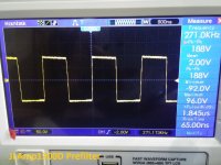
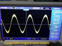
Testing the built-in bridge adapter of JLAmp1600D, paired with JLAmp1200D (identical gain).
Test setup:
Supply +/-85V DC (dropped to +/-70V @ full power)
Dummy Load: 8 ohms resistive (4 ohms test to follow)
Result:
88V RMS (below clipping)
968W @8ohms
Thick part of sinewave is the carrier frequency (330khz)
Test setup:
Supply +/-85V DC (dropped to +/-70V @ full power)
Dummy Load: 8 ohms resistive (4 ohms test to follow)
Result:
88V RMS (below clipping)
968W @8ohms
Thick part of sinewave is the carrier frequency (330khz)
Attachments
D
Deleted member 148505
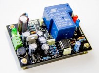
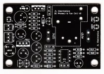
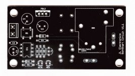
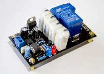
New version Softstart and Speaker Protect
New version of softstart and speaker protect. Fixes minor shortcomings of previous releases. (no pcb errors)
New version of softstart and speaker protect. Fixes minor shortcomings of previous releases. (no pcb errors)
- Simple design, easy to assemble, gets the job done.
- Low footprint, saves chassis space
Attachments
D
Deleted member 148505
New Products
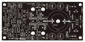
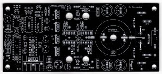
JLAmp1200D V2 PCB
- IR2110 driver
- For +/-100V DC rails
- Easier to assemble than previous version, no errors
- PCB size: 3" x 6.9"
- Thickness: 2mm
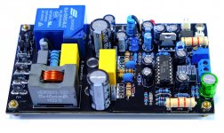
JLA-2092D L.E (JLA-250D V2)
- IRS2092 DIP16 driver
- For +/-75V DC rails
- 3 ohms to 8 ohms load
- PCB size: 2.8" x 5"
- Built in 20A speaker protect
- 2 modules can be bridged to get 900W @8ohms
JLAmp1200D V2 PCB
- IR2110 driver
- For +/-100V DC rails
- Easier to assemble than previous version, no errors
- PCB size: 3" x 6.9"
- Thickness: 2mm
JLA-2092D L.E (JLA-250D V2)
- IRS2092 DIP16 driver
- For +/-75V DC rails
- 3 ohms to 8 ohms load
- PCB size: 2.8" x 5"
- Built in 20A speaker protect
- 2 modules can be bridged to get 900W @8ohms
Attachments
Strange clipping issue when used with crossover
I'm having a problem with my JLAudiophile-250 board however I'm not convinced that the amp itself is the issue. Strange thing is though, when I swap out the JLAmp with a cheaper, less powerful IRS2092 based board, the problem goes away.
My speaker load can either be 2 or 8ohms. I chose to wire for 2ohms because I need more than 200 clean watts from +/-45v. The JLAmp is 2ohm stable as it’s using 2 IRFB5615’s
My power supply is a basic linear
300VA +/-45v
11,200uF / rail
My source is the balanced output of a mixer. I’m un-balancing the signal using a balanced line driver (SSM2142)
The amp seems to be operating as expected into both 2 and 8 Ohm speaker loads when it gets it’s input from the line driver as follows: Balanced Line Driver --> JLAmp --> Speakers
Wired in series (8ohms) I run into distortion before stressing the woofers. This was my expectation due to the limited voltage. (No issues here).
Wired in parallel (2ohms) is perfect. Plenty of headroom, very clean and strong bass. This too, is what I expected with sufficient current to drive the load.
I run into problems when I drive the JLAmp from my active crossover as follows: Balanced Line Driver --> Active X-Over --> JLAmp --> Speakers
Wired in series (8ohms) No change. it performs as it did earlier
Wired in parallel (2R), I get a harsh, cracking, distorted sound with every peak (even at moderate levels)
I've been ignoring the problem for some time now because I usually wire in series-parallel and it gets loud enough for everyday listening, I'm having a party on New Years Eve, so I want to figure this out asap.
Any ideas what the cause could be?
Last edited:
D
Deleted member 148505
Hi Darp, does the problem only occurs when it is connected to a balanced line driver?I run into problems when I drive the JLAmp from my active crossover as follows: Balanced Line Driver --> Active X-Over --> JLAmp --> Speakers
Wired in series (8ohms) No change. it performs as it did earlier
Wired in parallel (2R), I get a harsh, cracking, distorted sound with every peak (even at moderate levels)
I've been ignoring the problem for some time now because I usually wire in series-parallel and it gets loud enough for everyday listening, I'm having a party on New Years Eve, so I want to figure this out asap.
Any ideas what the cause could be?
Please add 100ohms 1/4W into the + input terminal of JLA-250D to avoid unwanted oscillations.
If the problem still persists, I'm suspecting that either the VCC supply or VSS/VAA supply is limiting the IRS2092 IC. The amplifier will shutdown for a second if it triggers OCP and will not produce crackling sound so OCP trigger is not an issue here. Also JLA-250D is tested to output 450W into 2 ohms at 120hz sine wave.
What resistor value did you put on R117/R118? If 3.3K 3W is installed (which is ok for your supply), the amplifier turns off at +/- 30V DC (9mA into VAA/VSS). Now if you put higher value, when your supply voltage is sagged at high power output, the VAA/VSS might be current limited.
Also since JLA-250D is using IRFB4615, it needs more current to drive the mosfets. Unlike default IRAUDAMP7 boards which uses IRF(B)4019.
If your power supply sags at high power output, VCC supply will be starved.
The R114 1.5K resistor in VCC regulator is limiting the current. Replace it with 10ohm 1W resistor. After replacing it with 10R resistor, there will be no current limiter for the VCC supply, so the oscillating frequency can be increased to more than 500khz. Be careful not to set the osc freq too high as the IC might be damaged do to overheating. Make sure the amp is running between 250khz to 350khz.
Regards,
Lester
- Status
- Not open for further replies.
- Home
- Vendor's Bazaar
- Amplifier Modules and PCBs For Sale