Yeah, I think the 4pairs should do just fine for most use.
I was only thinking about those extreme cases with hugely reactive loads, to make it as bullet proof as possible. But for now the 4pairs looks really good and robust enough.
The limiter should prevent the abuse that goes beyond what it can really do, and since that would only be in the rarest situations, it'll work.
I ran noise sims yesterday, after taking the reading on the damping factor, and found a SNR at a little over 123db. Not too shabby is it?
The 2n3055 and its complementary MJ2955 was an "all terrain" output transistor
The most sold amplifier in the 80s, the famous NAD 3020 used the same.
I am the owner of this amplifier, I just had to change the capacitors of the power supply and it still works like the first day.")
https://www.onsemi.com/pub/Collateral/2N3055-D.PDF
NAD 3020: Vintage hi-fi that still sounds great - CNET
The most sold amplifier in the 80s, the famous NAD 3020 used the same.
I am the owner of this amplifier, I just had to change the capacitors of the power supply and it still works like the first day.
https://www.onsemi.com/pub/Collateral/2N3055-D.PDF
NAD 3020: Vintage hi-fi that still sounds great - CNET
I've been trying for days to solve equations to calculate the values for the VI limiter, and so far I'm just not good enough at maths to get this done satisfactorily.
It's the simultaneous solving of a system of 2 equations that gives me the headaches right now, and if I could get that done and understand how to do it right, I could finally put this in a spreadsheet so I wouldn't get myself lost over and over in solving equations.
If anyone can help with the basic maths in solving this in a comprehensible way, that would really be great.
I've been trying to solve simultaneously those 2 equations:
( 1.507 * R2 ) / ( R2 + ( 220 * R1 ) / ( 220 + R1 ) ) = 0.6
R2 * ( ( 36.28 / R1 ) + ( 0.28 / 220 ) ) = 0.6
And I only get lost while doing it, getting nowhere useful. Anyone can give some hints please?
spooky
I can see that there might be a few issues trying to separate R1 and R2.
In this situation I'm more likely to use Newton iteration numerically rather than spend a few sides of A4 getting errors because a line was not copied properly, or a variable missed, etc.
How to solve:
Your functions must equate to zero. Swap the 0.6 to the left hand side to make this happen.
That allows you to define f(1)=xxx-0.6 and f(2)=yyy-0.6
Guess a value for r(1) and r(2). Perhaps 10k and 100.
Note I have now got your equations and resistors into an array or column matrix (1 column x 2 rows).
Define a Jacobian matrix (J(2,2)) by differentiating f1 and f2 by r1 and r2 i.e.
J(1,1)=df1/dr1;
J(1,2)=df1/dr2
J(2,1)=df2/dr1
J(2,2)=df2/dr2
You have to vary r1 and r2 in turn, and evaluate the effects of each on f1 and f2.
Then iterate by calculating an error dr=J(inverse)*f
I don't invert J but use LU decomposition to solve J.dr=f.
You write J=LU and so LU.dr=f, which you swap U.dr=z; that lets you solve Lz.=f for z,
then U.dr=z for dr. LU decomposition separates the matrix J into two half-matrixes L and U which when multiplied give J. Sounds complicated, but the code is straightforward. You can find LU decomposition methods on the Web or in most scientific/maths programming books.
You may have a scientific calculator that can solve a 2x2 matrix without this, but you'd have to write in the entries by hand.
Once you have calculated dr (that is, dr(1) and dr(2)) update r, using r(1)=r(1)-dr(1)
etc. and check when dr is very small, then stop.
Recalculate the functions and Jacobian entries with the new r's before the next iteration.
You would probably be able to do this in Excel using a macro for LU decomposition.
Incidentally I get R1=12.411k and R2=143 ohms.
Last edited:
In this situation I'm more likely to use Newton iteration numerically rather than spend a few sides of A4 getting errors because a line was not copied properly, or a variable missed, etc.
I've been trying many ways of doing this and got lost every time and things get much too complex to be manageable.
But I don't even know what a newton iteration is...
Your functions must equate to zero. Swap the 0.6 to the left hand side to make this happen.
At least that part isn't hard to do..
That allows you to define f(1)=xxx-0.6 and f(2)=yyy-0.6
Guess a value for r(1) and r(2). Perhaps 10k and 100.
So that means choosing one of the values already, and how do you put this into a spreadsheet?
Note I have now got your equations and resistors into an array or column matrix (1 column x 2 rows).
I tried ways to get to a matrix, but couldn't see how to do it.
And how can this be turned into spreadsheet formulae?
Define a Jacobian matrix (J(2,2)) by differentiating f1 and f2 by r1 and r2 i.e.
J(1,1)=df1/dr1;
J(1,2)=df1/dr2
J(2,1)=df2/dr1
J(2,2)=df2/dr2
I never heard of a jacobian matrix. So that's definitely going out of my "comfort zone". And wouldn't know what to do with this to make spreadsheet formulae.
You have to vary r1 and r2 in turn, and evaluate the effects of each on f1 and f2.
So there is no way to get to a result with 2 values for the 2 unknowns?
If one value has to be picked, then it's kind of like turning the equations with 2 unknowns into only 1 unknown.
Then iterate by calculating an error dr=J(inverse)*f
I'm definitely lost here.
You may have a scientific calculator that can solve a 2x2 matrix without this, but you'd have to write in the entries by hand.
Nothing of the kind. I used to have a TI30 in my early school years, which isn't much and is long gone. Also a TI57, which was more fun but the battery died and I couldn't fix it. So nothing else of that nature. Just a computer.
But maybe there is a way, perhaps using something like MathPad, Mathematica or MatLab? But that's something I have no experience using, and I'd have to figure that out too.
The key is to arrive at something that can be turned into spreadsheet formulas, so once it's done, it can be used to recalculate the values over and over, and vary certain things, like rail voltage or whatever...
You would probably be able to do this in Excel using a macro for LU decomposition.
That's the main goal, to avoid having to redo all this and re-learn it all every time. But how?
Incidentally I get R1=12.411k and R2=143 ohms.
This is where we should end up, in a spreadsheet. And then by changing things, get the new values. If the breaks in the locus is changed, the chosen threshold for the Vbe (0.6, 0.65V or whatever) is tweaked, rail voltage changes, etc...
Actually, I guess you've noticed we're trying to add a proper protection on the grounded bridge you proposed quite some time ago.
Very nice design and works quite nicely, but needs proper protections to make it as bullet proof as possible.
This is going to make for a very nice build.
I want to add a limiter on it to sense when too much distortion is present and act on the amp's input to mitigate. I think using an opamp to sense the difference between the inputs on the input diff stage should work well, and then use that to trigger action on the amp's input to limit it. This should work to limit hard clipping, but also other things, like issues with overly hard and complex loads, as well as when the VI limiter is acting...
Having a level limiter working in concert with the VI limiter should make it work better than with just the VI limiter alone. And things like clipping can be mitigated as well.
I wish I was better at maths. I'm trying to get better..
spooky
Excel has some matrix functions you might be able to use. THere is a thing called MINVERSE and MMULT to find the inverse of a matrix (so you don't have to use LU decomposition. Excel might use that internally though) and multiply the result by your functions to find the error dr.
You can write the formula into Excel cells. Add a couple for r1 and r2. To work out the differentials I add 1 and subtract 1 from each r (another two cells each). Then for each of these work out the f1 and f2 function values
Then in other cells next to each other fill in the Jacobian as in my earlier post, in a 2x2 block of cells like
df1/dr1 df1/dr2
df2/dr1 df2/dr2
Note df1/dr1=(f1(calculated with r1+1) - f1(calculated with r1-1))/2
since the difference in r is now 2 (ohms).
You should be able to use MINVERSE to invert this 2x2 matrix.
Then use the result to calculate the error in the guess. FOr example
error in r1=MINV(1,1)*f(1)+MINV(1,2)*f(2)
error in r2=MINV(2,1)*f(1)+MINV(2,2)*f(2)
assuming MINV is the 2x2 matrix returned after inverting.
that will give you the errors to be added to r1 and r2.
If you want, you can add the errors to r1 and r2 back to r1 and r2, but this needs Excel to be persuaded to use iteration. That is available in options.
Hope this helps.
I can't upload a spreadsheet, but I can provide the pdf image.
The resistor values (guessed) are entered top left. Next are the incremented and decremented values.
Below are the two formulas. To the right are each formula calculated with the varied resistances.
Below that are the Jacobians, taking the difference between the functions and divided by the difference in the resistances (2 ohms here).
After that the minverse function is used to calculate J(inverse) which on the last section but one mmult is used to multiply the inverse by the original functions.
That leads to the two error values, which you subtract from the original resistors to give an updated value. Put these into teh cells for r1 and r2 will give another improvement etc.
To iterate this, put the result of the mmult back into the resistor boxes, but to do that successfully you will need to set up for iteration.
Attachments
Hi Spooky,
Apologies for the delay in getting back to you.
I found it easier to derive the equations in general form.
I’ve attached my spreadsheet derived from MK’s analysis at Fig 3 to generate R1 and R2. These values can then be modified to use standard resistor values, and entered into another table to draw a new locus which is compared to the original The values Vcc(Vrail), VceA(0V), VceB (36V), IcA(6.85A), IcB(4A) are as given in the article.
I've modified my VI limiter spreadsheets to conform to your needs ie dual and triple slope of 4 x 2N3055 at 75C. Please PM me your details
Brian.
It seems I can’t upload an xls file, so I’ll have to send it to you
Here's a pdf of said spreadsheet.
This looks pretty good and if we can push things a bit further to take care of other more complex topos, we could get a powerful tool that would save us all a lot of time and frustration.
I'm going to clean up the current sim so it can be as clear as possible for posting here. It will have the limiter circuitry that I'm proposing to use. None of the values are properly calculated yet, and I disabled the limiter to run the sim cleanly, but I will re-enable that part before posting it. The values needed for the limiter will be param lines for easy updating.
what are the results of testing if the 2N3055's are replaced with common 2SC5200 transistors? I would suspect 50 - 100x better.
Do you mean testing the sim with those other outputs?
I haven't tried that for that sim, but did something like this for other sims, and depending on the parts, there are sometimes improvements, and sometimes it takes some updating for other part values to make it work again.
Improvements can be somewhat important, but I doubt 50 or 100x better. Not likely.
Not too awfully long ago, I built up a simple 2N3055 amplifier running off +/-32V. Powered by a 22-0-22 650 VA toroid meant to power 12 gainclones simultaneously. Simple diff pair, single ended VAS with a 6 mA current source, and the same output triple used in the Phase Linear, with 3 actual 2N3055’s per bank. It had absolutely no trouble with a 2 ohm load - that is, 4 speakers in parallel, turned up to abusive levels. I really don’t think you’ll need to go to 5 transistors per bank.
Those 3055s are pretty robust, as long as we make sure they're not taken too far.
A 3 pairs version of the grounded bridge probably would be fine on an 8ohms load, if it's not an overly difficult one, like electrostatic speakers of whatever.
I'm aiming for the 4 pairs version, so it can be bullet proof, as much as possible, with all the protections we can come up with: VI limiter, input limiter/compression, thermal sensing, DC detection, output and input muting, SSRs for rails and amp output. I think there might be a good reason to use a micro-controller to handle all those things and do proper power-up and shutdown, as well as handling faults, in a proper sequence.
Here it is, the latest 3055 grounded bridge sim with the VI limiter reconnected.
Don't pay attention to the values for everything in the limiter, as nothing has been calculated yet, including the zener choices. Although the current sources I put on them should work as they are now..
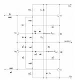
The overall scheme for the limiter is basically the 3 slopes from M.K, attached, except that I put the zeners on current sources, which shouldn't change anything to the calculations for the limiter itself.
I think this time it's going to work, with both sides of the bridge having its own limiter. It wouldn't work before, because I was trying only on the high side.
If someone wanted at some point to build this using other trannies than the 3055/2955, there may be a few things to adjust if the rails are higher, and then the limiter would require recalculation of course. But this could be done.
Don't pay attention to the values for everything in the limiter, as nothing has been calculated yet, including the zener choices. Although the current sources I put on them should work as they are now..
The overall scheme for the limiter is basically the 3 slopes from M.K, attached, except that I put the zeners on current sources, which shouldn't change anything to the calculations for the limiter itself.
I think this time it's going to work, with both sides of the bridge having its own limiter. It wouldn't work before, because I was trying only on the high side.
If someone wanted at some point to build this using other trannies than the 3055/2955, there may be a few things to adjust if the rails are higher, and then the limiter would require recalculation of course. But this could be done.
Attachments
Those 3055s are pretty robust, as long as we make sure they're not taken too far.
.
Quite often they are run near the limit which can blow them if you get a spike on the power supply. A 220uF and 100nf on each power rail help to damp the rail spikes.
I stupidly built mine without the extra caps and at the first sign of a mains spike it blew up.
Quite often they are run near the limit which can blow them if you get a spike on the power supply. A 220uF and 100nf on each power rail help to damp the rail spikes.
I stupidly built mine without the extra caps and at the first sign of a mains spike it blew up.
Ouch!
Well, the plan is an all-on-one-pcb with all the trimmings and the least amount of external wiring possible. So we'll have to make sure to put caps everywhere they're needed.
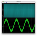
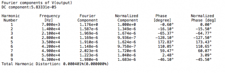
3055 bridge SMPTE IMD
Here is a sim I just ran with the limiter re-connected, although no values have been calculated, they've been made to prevent it from acting on legit signal, so it's not bothering anything and I can get a normal result.
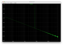
This is a sim for IMD using the SMPTE method, with the 60hz/7k at 4:1, and adding a 60hz notch filter at the output to get a clean FFT view.
Looks pretty good to me.
If I'm doing something wrong, please don't hesitate to croak please
Here is a sim I just ran with the limiter re-connected, although no values have been calculated, they've been made to prevent it from acting on legit signal, so it's not bothering anything and I can get a normal result.
This is a sim for IMD using the SMPTE method, with the 60hz/7k at 4:1, and adding a 60hz notch filter at the output to get a clean FFT view.
Looks pretty good to me.
If I'm doing something wrong, please don't hesitate to croak please
Attachments
I "discovered" 2n3055 in an Allied electronics catalog about 1968 but I didn't understand the issues with SOA until many years later. I and others dreamed of making 55 Watt amplifiers with them, but such amps survived for about 5 minutes. 2N3055 is rated 60V so we thought we could make an amp with +/-30VDC or 30*30/8/2 = 56.25 Watts. But the realities of secondary breakdown mean that you are pushing these at +/-20VDC (20*20/8/2=25 Watts @ 8 Ohms). An actual 2n3055 is not a big transistors if you tear one apart. But there have been many similar named parts (TIP3055 etc) that are probably bigger and more powerful because vendors needed to make a "2n3055" that actually worked in the hundreds of overly optimistic designs. Ie don't tell the designer that he is an idiot, just tell him your 2n3055s are better. Much better for business.
So my advice is to take the classic quasi-comp circuit, add a current mirror and a Darlington VAS and run it at +/-20VDC. It's a good idea to include current limit. Enter it into spice and tinker with values to optimize performance. Step through temperature from 20 to 80 C and check for idle bias stability.
So my advice is to take the classic quasi-comp circuit, add a current mirror and a Darlington VAS and run it at +/-20VDC. It's a good idea to include current limit. Enter it into spice and tinker with values to optimize performance. Step through temperature from 20 to 80 C and check for idle bias stability.
...other more complex topos, we could get a powerful tool that would save us all a lot of time and frustration.
Hi spookydd,
Here's a pdf of your desired VI limiter (MK's Fig. 44), with standard component values inserted. I'll post the full range of spreadsheets to your address, now that I have it.
Brian.
Attachments
Last edited:
- Home
- Amplifiers
- Solid State
- Amplifier based on 2N3055