So what are you talking about?
A grounded bridge. Based on 3055s (and 2955), with supply at 70V rail to rail. (no center point).
A grounded bridge, with 70V rail to rail can deliver well over 200W in an 8ohms load (resistive).
And for the power hungry, a grounded bridge, can be in turn, bridged, again...
There is another possibility for making a high power amp using 3055’s. A Super-Leach style amp on +/- 70 volts. This can be bridged as well. Would it have any advantages or disadvantages compared to the grounded bridge? Don’t know. It would require full voltage transistors for the VAS and input stage. VAS could be single ended with a bootstrap, if you didn’t want to splurge a whole dollar on a high voltage 20 watt PNP. Would require a split supply instead of just a single voltage. It would have the advantage of using ordinary VI limiters - I’ve used them on stacked output stages and they work fine.
Yes! You're right! That's an other way to do it. And it should work nicely as well.
The input stage being cascoded also helps using low voltage low noise parts, but not the vas, as you mentioned.
It could be bridged as well. Uses more common VI limiters and does require a split supply.
Pros and cons on both, but both are feasible. Maybe when we make the grounded bridge work, we could take a look at the leach superamp afterwards. More 3055 projects for the aficionados...
And there is one more 3055 project that I definitely would like to try after that: a bryston style 3055 amp. Which I've been simulating for quite some time and the performance is stunning. Not as much power output, but very low thd and the bryston style protections are different and don't need to be redesigned.
I've been digging into making the VI limiter work on the grounded bridge and I think I should be able to make it work now. I found things to do, finally, that should put an end to the fighting that prevents the limiter from acting properly.
There is no way around it. Being a bridge, with 2 sides, both sides have to get their own limiter sensing in place, and both vas have to be protected themselves and acted upon.
Once that's done, it should work like on a normal amp.
So I'm working on making it a 3 slope limiter. I verified already that the added protection on the vas (both) does work and forced a simplified limiter to act, so see how it goes, and that worked. So there may be a light at the end of the tunnel.
Now remains to be done the calculations for the breakpoints to match the locus that I plotted on that soa curve...
After that, we'll have to look at adding ssr switches on the supply and output. I think only one side of the supply needs to be switchable, since that supply has no center tap, breaking one side would break the whole thing, and if acting as well on the ssr on the amp output, that should be an effective protection. This type of protection is more aimed at the DC situation, not really the short or overload/clipping situation.
DC detection requires very immediate shutoff, while shorts or overloads and clipping shouldn't cause the full stop, just the foldback until the fault is remedied.
For the clipping and overload situations, I think that what I was looking into should be workable, with a simple opamp to do the sensing, and then use that to limit the amp input, so it would be a limiter. And this would combine with the VI limiting when the overload is caused by an overly hard load, like too reactive with an overdrive on it...
The ssr on the amp output can easily be used in conjunction with the input limiter as a muting function. That can be used in a soft start and shutdown protocol, so the amp doesn't connect to the speakers until it's fully ready.
The goal is to make this amp as bullet proof as possible, and if done right, possible indestructible (hopefully), so any abusive usage won't bother it and it can be used by anyone for P.A.
I did some simulations a few years back of the super leach with 3055s, and made that work.
Maybe to speed up a development process there is no need to reinvent the wheel and make use as is of a good pcb layout that someone must've done already.
The only thing needing some calculations would be the VI limiter to be tailored to the 3055 situation.
I think that's a nice project as well. And for kicks, a good protection scheme beyond the VI limiter could be added as well, like ssr on rails, on output, limiter for clipping and overload...
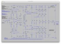
Here is a snapshot of that leach super amp 3055 based sim that I did long ago.
As with any leach amp sim, it doesn't simulate totally well, with some issues and thd performance isn't stellar. But that's how the leach amp simulates anyway, so this should be a working amp to build.
As with any leach amp sim, it doesn't simulate totally well, with some issues and thd performance isn't stellar. But that's how the leach amp simulates anyway, so this should be a working amp to build.
Attachments
but how to derate that? Anyone can offer some insight?
The low segment of the locus may have to be moved slightly down to accommodate for the second breakdown..
Is this of some help?
General form equation for the Ic/Vce log-log gradient is Ic=k(Vce)^n
where
n = (logy1-logy2)/(logx1-logx2)
k = y1/(x1)^n
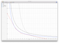
For a 2N3055, by inspection from the log-log SOAR graph, the second breakdown segment has co-ordinates x1,y1 at 40V, 2.88 A and x2,y2 at 60V,0.8A respectively.
Thus k=325803 and n = -3.1549
So Ic = 325803*Vce^(-3.1549) at 25C.
I’ve seen data that extrapolates the Tjmax for second breakdown of a TO3 device as around 330C, so the de-rating factor at 75C becomes 0.836 (ie (330-75)/(330-25)).
So Ic = 0.836*325803*Vce^(-3.1549) at 75C. (ie y = 0.836*325803/(x^3.1549)
I derived an Excel spreadsheet many years ago for these calculations and for the associated VI locii, but the attached show plots via a graphing calculator. (spookydd, which graphing calculator did you use?).
As an aside, an explanation for the other curves might be useful to some.
The thermal gradient usually follows the law Power(P) = Vce*Ic, so Ic = P/Vce.
(thus P=Vce^-1, so from above k = P and n = -1).
In this case (2N3055) P=115W, so Ic = 115/Vce or y=115/x, as displayed.
The temperature de-rating factor is (Tjmax-Tcθ)/(Tjmax-Tc25), if θ is >25.
Tjmax = 200C for a TO3 device thermal gradient, and here θ is taken as 75C so the factor becomes (200-75)/(200-25) = 0.714.
The de-rated power thus becomes 0.714*115W, or 82.11W at 75C
Be aware, though, that some devices do not exhibit the constant power law; don’t blithely assume it. Check the product of Vce and Ic at the extremes of the gradient, if equal then the law applies ( provided the gradient is a straight line). A substantial variation would require that the equation Ic=k(Vce)^n be similarly employed, as described above, using the thermal gradient co-ordinates.
Brian
Attachments
Last edited:
Is this of some help?
I hope. I will have to read this over and over to digest it ;-)
I derived an Excel spreadsheet many years ago for these calculations and for the associated VI locii, but the attached show plots via a graphing calculator. (spookydd, which graphing calculator did you use?).
Was that spreadsheet shared somewhere?
I discovered just a few days ago that I had that little "grapher" utility that can plot curves and that's what I used for the plots I shared earlier.
I was thinking about excel, but although I use it for many common things, doing such plotting with it isn't familiar to me enough yet.
What else to use?
As an aside, an explanation for the other curves might be useful to some.
The thermal gradient usually follows the law Power(P) = Vce*Ic, so Ic = P/Vce.
(thus P=Vce^-1, so from above k = P and n = -1).
In this case (2N3055) P=115W, so Ic = 115/Vce or y=115/x, as displayed.
The temperature de-rating factor is (Tjmax-Tcθ)/(Tjmax-Tc25), if θ is >25.
Tjmax = 200C for a TO3 device thermal gradient, and here θ is taken as 75C so the factor becomes (200-75)/(200-25) = 0.714.
The de-rated power thus becomes 0.714*115W, or 82.11W at 75C
This should definitely help. But it'll take a little time and repeated readings to make sense of it.
By the way, long ago, you mentioned having built a spreadsheet, based on M. Kiwanuka's VI paper, to calculate limiters. Was that shared somewhere?
Does it calculate the values? For which limiter type? (slopes...)
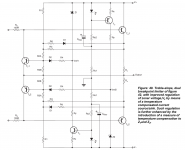
I'd like to calculate the values for a limiter such as the one attached here:
Attachments
It turns out it's a pain to use that grapher utility. It's not much of a calculator, although it does plot the curves from equations and tables of values.
It allows defining limits for the axes, but then it doesn't obey that in the display.
When we add text annotations and place them on the plot, they disappear when the file is reloaded later, and whatever happens to remain isn't where we had placed it.
Too much trouble. So what to use instead?
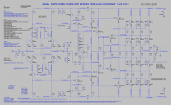
I'm posting what I'm trying to do now, but it's not complete and many things, like text annotations have disappeared, again, and it's been impossible to get the axes limits displayed properly, it doesn't use what we set and does whatever it wants.
It allows defining limits for the axes, but then it doesn't obey that in the display.
When we add text annotations and place them on the plot, they disappear when the file is reloaded later, and whatever happens to remain isn't where we had placed it.
Too much trouble. So what to use instead?
I'm posting what I'm trying to do now, but it's not complete and many things, like text annotations have disappeared, again, and it's been impossible to get the axes limits displayed properly, it doesn't use what we set and does whatever it wants.
Attachments
With the super-amp topology I had envisioned using four heat sinks per channel, each with 3 TO-3’s and a TO-220. Non isolated, and mounted directly to the PCB. Why? I already have said heat sinks, pre drilled, and PCB mountable. When doing that, you must separately compensate the Vbe’s because they may not track temperature perfectly. The Leach vbe multiplier with diodes in it works well for that with two diodes (or diode connected BD139’s) on each master heat sink. The slaves don’t need compensation. Put an insulator spacer between the boards, heat sink to heat sink, and clam shell them together soldier side out. Force air thru the center. Have the fan run on low all the time and increase speed at some temp, say 60C.
Would anyone have in pdf the article from M. Kiwanuka that was published way back in the september 2002 electronics world?
I know this is very old stuff. I have the article from the next issue, but I'd like to get the previous one.
The amended article is available at Bonsai's site, but I've attached the original. Note that his triple slope arrangement in the original, Fig 42,the one you are interested in, has been superseded by Fig 44.
I'll get back to you re your questions. Some answers may be in the spreadsheet I sent you back in 2013
Brian
Attachments
With the super-amp topology I had envisioned using four heat sinks per channel, each with 3 TO-3’s and a TO-220. Non isolated, and mounted directly to the PCB. Why? I already have said heat sinks, pre drilled, and PCB mountable. When doing that, you must separately compensate the Vbe’s because they may not track temperature perfectly. The Leach vbe multiplier with diodes in it works well for that with two diodes (or diode connected BD139’s) on each master heat sink. The slaves don’t need compensation. Put an insulator spacer between the boards, heat sink to heat sink, and clam shell them together soldier side out. Force air thru the center. Have the fan run on low all the time and increase speed at some temp, say 60C.
Why not? If you have the stuff already, better use it than buy new stuff ;-)
How do you plan on making the diodes make good contact with the sink? With holes through them like some did who made the leach?
Maybe there are usable diodes in a TO126 case that could be used instead, making far better contact and making the assembly easier and more straightforward. No need for extra drilling and making plastic round diode case make thermal contact with a sink...
The amended article is available at Bonsai's site, but I've attached the original. Note that his triple slope arrangement in the original, Fig 42,the one you are interested in, has been superseded by Fig 44.
I'll get back to you re your questions. Some answers may be in the spreadsheet I sent you back in 2013
This one has a different page count from the one I have, and I think I got it from bonsai's site before. Maybe some updates were made, but which is newest?
I'll look at this closer tomorrow.
It's been a long time since I've worked on this. I have to refresh my memory.
But if I have some spreadsheet from years ago, either it wasn't calculating all the values for the resistors, or it was just doing the single slope or something like that.
I'm aiming towards the 3 slopes right now. Many more calculations to handle. So a spreadsheet would definitely speed things up.
I tried making a spice test rig for the limiters. In different ways, including one trying to do what Doug Self mentions and also based on the example at the end of M.K.'s paper. But that doesn't work so well. I don't think either were using ltspice to begin with, so there has to be something different..
How do you plan on making the diodes make good contact with the sink? With holes through them like some did who made the leach?
BD139 transistor with the base shorted to collector. Easy mounting, no insulator, no muss no fuss. It’s too bad the TO-126 case is going away. The 139/140 pair will probably be the last hold out before it’s finally obsoleted. Most of them are already gone. There’s always the fully insulated TO-220, but most of those have a bit too large a die in them. You don’t really need or want a 10 amp diode - not enough drop and it will end up being overcompensated.
BD139 transistor with the base shorted to collector. Easy mounting, no insulator, no muss no fuss.
Yes! Definitely!
I like that better than the diodes. The thermal sensing can only be much better that way, and the mounting so much easier and more secure.
It’s too bad the TO-126 case is going away. The 139/140 pair will probably be the last hold out before it’s finally obsoleted. Most of them are already gone. There’s always the fully insulated TO-220, but most of those have a bit too large a die in them. You don’t really need or want a 10 amp diode - not enough drop and it will end up being overcompensated.
Well, if you look at it this way, the TO3 case is also being phased out.
And even most through hole stuff is pretty much being pushed out the door in favor of surface mount stuff.
Personally I can't deal with surface mount, and for anything DYI, we really want to stick with the through hole stuff anyway. And since there are still many parts being made now as through hole, the phasing out will take some time.
So we use what's best for us and if something isn't manufactured, we still can get left over or old stock somewhere.
I have several sims of the leach amp, several using the 3055s and there were mods made to the original leach version to make it more stable, work far better in sims and I think we may even have replaced the bias diodes by something else... We'll have to take a look at this again.
The super leach really doesn't work well as is in sims, and the performance isn't stellar either, but a few little tweaks and it can be turned around.
Do you do any pcb layout?
The amended article is available at Bonsai's site, but I've attached the original.
So the one on Bonsai's site would be newer then?
Anyway, I was looking for the article published in the september 2002 electronics world, because having read the next one in the october issue, which is the continuation, I found it more elaborate than this full paper in pdf.
The october article is going more into details for the more complex limiters, with more calculation examples done, so I assume the first part would also be a little more explanatory..
Some answers may be in the spreadsheet I sent you back in 2013
Is this the spreadsheet? (attached here)
This is very nice and is a good tool to help in the calculations. And very nice SOA plotting. But we could add the plotting of the wanted locus, and it's missing the actual calculations of the parts to make it work as described.
What I had in mind is a spreadsheet that can give all the values to all the parts involved.
Of course it would have to be geared for a specific topology, and I guess several versions of topologies could be included, to be more thorough.
The single and dual slopes would be a minimum, but we could also have the more complex ones.
This would be a great tool, to avoid spending so much time every single time a limiter needs to be calculated.
Attachments
With the super-amp topology I had envisioned using four heat sinks per channel, each with 3 TO-3’s and a TO-220. Non isolated, and mounted directly to the PCB. Why? I already have said heat sinks, pre drilled, and PCB mountable. When doing that, you must separately compensate the Vbe’s because they may not track temperature perfectly. The Leach vbe multiplier with diodes in it works well for that with two diodes (or diode connected BD139’s) on each master heat sink. The slaves don’t need compensation. Put an insulator spacer between the boards, heat sink to heat sink, and clam shell them together soldier side out. Force air thru the center. Have the fan run on low all the time and increase speed at some temp, say 60C.
I found what I think was the latest sim for the tweaked version of the superleach with 3055s. That sim works with no issues.
But the bias diodes are still there. I thought maybe we had replaced them with something else, but I was mistaken.
Still, I guess there should be no problem doing that, using bd139 as diodes. The amp has 4 bias diodes, the same number as your planned heatsinks, so no problem there.
Attachments
How do you plan on making the diodes make good contact with the sink? With holes through them like some did who made the leach?
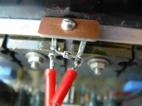
I found that only three diodes were needed on my Leach. I mounted them with four leads clamped directly to the heatsink, via a Kapton tape insulator, as shown.
Try a not very scientific test to see why:
Hold the diode body between thumb and finger. Apply a hot soldering iron bit to the lead. Time your “ouch, better drop it” response as the body (and fingers) heats up. Now do the same but hold the opposite lead instead of the body. Betcha drop it sooner!

There are thus three PN junctions that respond much faster to the heatsink temperature change than does the glass or resin diode bodies. It probably responds better than any clamped TO126, unless perhaps the collector lead is clamped?
Bonsai’s site carries the latest revision of Michael Kiwanuka’s (MK) article, as far as I am aware.
I’ll have to check the contents of the spreadsheet I sent you; it may not be complete, from the sounds of it. I’ll post a more detailed version, calculated for your device
I derived spreadsheets for all the VI limiters and plotted them onto the Vce/Ic graph in Excel. I used MK’s method of analysis to derive general form equations to determine limiter device values that modify instantly the plotted VI locus as they are varied.
Will be in touch.
Brian
Attachments
Last edited:
I found that only three diodes were needed on my Leach. I mounted them with four leads clamped directly to the heatsink, via a Kapton tape insulator, as shown.
Wow! So that means you're sensing the heat from the sink via the leads and not the diodes' bodies. The length of those leads must be important, affecting the response delay.
What bothers me with using diodes is that flimsy mechanical mounting system.
Bonsai’s site carries the latest revision of Michael Kiwanuka’s (MK) article, as far as I am aware.
So that makes the one you sent a prior version. Always good to have anyway.
I’ll have to check the contents of the spreadsheet I sent you; it may not be complete, from the sounds of it. I’ll post a more detailed version, calculated for your device
I derived spreadsheets for all the VI limiters and plotted them onto the Vce/Ic graph in Excel. I used MK’s method of analysis to derive general form equations to determine limiter device values that modify instantly the plotted VI locus as they are varied.
Sounds awesome!
If several limiters are calculated, we can compare them as well. And this could help decide which to choose...
Sometimes it may not be a clear benefit to use a 3 slopes instead of a 2, or single.
Wow! So that means you're sensing the heat from the sink via the leads and not the diodes' bodies. The length of those leads must be important, affecting the response delay.
The leads protrude merely to show them. They fit snugly against the H/S, with almost their full length clamped. In addition the sleeving covers the leads and body, reducing heat loss and improving rigidity
Sometimes it may not be a clear benefit to use a 3 slopes instead of a 2, or single.
MK suggests that a three slope is overkill for rails below 40V. I've found that, depending on the Vce/Ic curve, single can be good enough, particularly when multiple OP's are used
Brian
- Home
- Amplifiers
- Solid State
- Amplifier based on 2N3055