annex666 said:...here's a thought - if you want to create an amp from scratch the first thing you have to do is create a universe.

I don't think DocP was being literal - most people here probably know that sound needs a medium to travel through - and yes I too hate it when they put such huge explosions in space films, although it does make some nice rumbles
Here's a great site for griping about stupid special effects in movies
http://www.intuitor.com/moviephysics/
Anybody ever try the "ready-made" softstarts available? I am thinking essentially things like:
http://www.atmel.com/atmel/acrobat/doc3a9114d9cbe55.pdf
http://www.melexis.com/site/products/pdf/90805.pdf
It seems one can pretty much get them to ramp up the voltage at user-defined times. External triac can be chosen to suit power switched and the softstart is automatic at power on.
Does anybody have any experience?
/UrSv
Try the soft start circuit used in the A75 Power Supply by Pass/Thagard.
http://www.passdiy.com/legacy.htm
Anthony
http://www.passdiy.com/legacy.htm
Anthony
Well, He could always put a relay in the mains and shunt in a diode in the hot side of the supply. The relay would be on a 10 or 15 second timer circuit then switch off which will short the diode and supply normal voltage.
The Diode in circuit will only allow the transformer to run at half input voltage, then when shorted the Transfomer will run at full input. A nice soft start.
You could use a 555 timer, or all in one relay to cut the Diode in and out of the circuit.
Anthony
The Diode in circuit will only allow the transformer to run at half input voltage, then when shorted the Transfomer will run at full input. A nice soft start.
You could use a 555 timer, or all in one relay to cut the Diode in and out of the circuit.
Anthony
Yeah, i don't think this does anything to reduce the inrush current, which is the goal here. The output voltage will still be the same too, only you'll have 60 charging pulses per second instead of 120 (or 100 for you Europeans). If you're going to the trouble of using a relay to short out your current limit device, it would be easier to just use a thermistor or even just a fixed power resistor.
Although the resistance of a thermistor will be pretty low after it heats up, you can still eliminate this small resistance with the relay. A secondary benefit of shorting the thermistor is that if the amp is rapidly switched off and on, it will successfully limit the current - a problem with the non-shorted arrangement that doesn't allow the thermistor to cool off. Of course, you will need to ensure that the relay timer circuit resets properly, but that's not hard to do.
Although the resistance of a thermistor will be pretty low after it heats up, you can still eliminate this small resistance with the relay. A secondary benefit of shorting the thermistor is that if the amp is rapidly switched off and on, it will successfully limit the current - a problem with the non-shorted arrangement that doesn't allow the thermistor to cool off. Of course, you will need to ensure that the relay timer circuit resets properly, but that's not hard to do.
For those who would lose sleep over their speakers not being protected from amplifier fault conditions and turn on/off thumps, whatever design they may choose, as to the choice of a good relay, Omron introduced a few years ago, a premium relay designated Omron G5Z. This features a solid gold bar in place of the usual reed contacts. The company claimed that it potentially degrades sonics in the least and was designed specifically for audio amplifiers, with sonics in mind.
Elektor has published a circuit along with their 1000watt Mosfet amplifier design, that features a soft start, DC protection and Speaker muting at turn on/off - a kind of all in one function. You can even add thermal protection to this circuit. If I can find the magazine, I will post a scan of the schematic and the PCB design which should make many happy. I have used this circuit in conjunction with many amplifiers, since the protection circuit uses its own power supply, and I think it is a very reliable circuit. For those whose amps have seldom or never failed and who go with only a primary side fuse, this should never matter. In this case, the way to go would be to eliminate input sockets (RCA/XLR), output binding posts (5 way/Speakon etc.,) and direct solder all connections atleast on the amplifier PCB. Yes, I can vouch that it does sound different, more neutral to be exact, provided the audio chain has sufficiently high resolution.
Elektor has published a circuit along with their 1000watt Mosfet amplifier design, that features a soft start, DC protection and Speaker muting at turn on/off - a kind of all in one function. You can even add thermal protection to this circuit. If I can find the magazine, I will post a scan of the schematic and the PCB design which should make many happy. I have used this circuit in conjunction with many amplifiers, since the protection circuit uses its own power supply, and I think it is a very reliable circuit. For those whose amps have seldom or never failed and who go with only a primary side fuse, this should never matter. In this case, the way to go would be to eliminate input sockets (RCA/XLR), output binding posts (5 way/Speakon etc.,) and direct solder all connections atleast on the amplifier PCB. Yes, I can vouch that it does sound different, more neutral to be exact, provided the audio chain has sufficiently high resolution.
Hi all
hifiZen wrote:
I can agree with that, since without any inrush current limitation, the largest current spike will accour during the first half cycle that is applied to the primary of the transformer. And with a diode you can't overcome this.
But matters would be even worse: You do in fact rectify the voltage feeding the transformer's primary, resulting in a pulsed DC current. Which I think the transformer wouldn't like that much. I intentionally simplified things a bit here.
The simplest inrush current limiting circuit I've ever seen was consisting of a resistor and a relay. The resistor is in series with the transformer's primary and the relay contact in parallel with this resistor. The relay coil (which must be apropriate for the respective mains voltage) is wired in parallel with the transformer's primary. The relay's intrinsic turn-on delay together with the slower voltage buildup caused by the voltage divider (resistor/transformer) on it's coil give the necessary delay.
With amplifiers that draw a lot of current even under idle condition (i.e. class A) this circuit might probably not work as intended. So it might be better to put the relay coil on the mains side of the series resistor but then the delay time is determined solely by the relays intrinsic switch-on delay. It would be even better to add some electronic delay in this case.
Regards
Charles
hifiZen wrote:
Yeah, i don't think this does anything to reduce the inrush current, which is the goal here. The output voltage will still be the same too, only you'll have 60 charging pulses per second instead of 120 (or 100 for you Europeans).
I can agree with that, since without any inrush current limitation, the largest current spike will accour during the first half cycle that is applied to the primary of the transformer. And with a diode you can't overcome this.
But matters would be even worse: You do in fact rectify the voltage feeding the transformer's primary, resulting in a pulsed DC current. Which I think the transformer wouldn't like that much. I intentionally simplified things a bit here.
The simplest inrush current limiting circuit I've ever seen was consisting of a resistor and a relay. The resistor is in series with the transformer's primary and the relay contact in parallel with this resistor. The relay coil (which must be apropriate for the respective mains voltage) is wired in parallel with the transformer's primary. The relay's intrinsic turn-on delay together with the slower voltage buildup caused by the voltage divider (resistor/transformer) on it's coil give the necessary delay.
With amplifiers that draw a lot of current even under idle condition (i.e. class A) this circuit might probably not work as intended. So it might be better to put the relay coil on the mains side of the series resistor but then the delay time is determined solely by the relays intrinsic switch-on delay. It would be even better to add some electronic delay in this case.
Regards
Charles
Check out this link,
http://jaycarstore.webfactory.com.a...car(directory)***.ws4d?jaycar/results(S).html
Its a dc protection and thump supression etc kit from Australian site Jaycar.com.au, price is about 25 australian. Good price and looks ok?
http://jaycarstore.webfactory.com.a...car(directory)***.ws4d?jaycar/results(S).html
Its a dc protection and thump supression etc kit from Australian site Jaycar.com.au, price is about 25 australian. Good price and looks ok?
Yet another speaker protection circuit
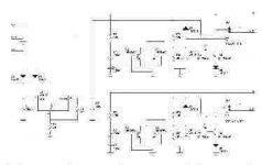
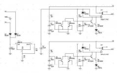
I refer to Iceman's circuit. It is simple, and will do the job. However, it has one deficiency compared to Peter Daniels'. It may introduce crosstalk between the two channels as both output are connected through R6 and R7. Although Peter's circuit is very good, this is a bit too complicated to build.
I obtained this compromised version from DIY Zone from Taiwan:
http://www.diyzone.net
unfortunately, the site is in Chinese only.
The circuit is very simple: in essence, it is an isolated and duplicated Iceman circuit, plus a latch to keep the relay deenergized if DC is detected. The good thing is that the circuit operates independently, allowing one to identify the failed channel easily. The only draw back is you have to synchronise the time delay of the two channels by adjusting R3/R4 and R6/R7 combination.
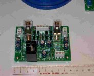
I build two of these (from the PCB purcahsed from DIY Zone). The first one I spend hours adjusting the resistor combination, but thinking of it I don't think it's worth the effort. The second one I just tried to match all resistors and capacitors beforehand. The result is that the two relays are turned on out of sync, with a 0.5 second difference. I guess I can live with that.
I refer to Iceman's circuit. It is simple, and will do the job. However, it has one deficiency compared to Peter Daniels'. It may introduce crosstalk between the two channels as both output are connected through R6 and R7. Although Peter's circuit is very good, this is a bit too complicated to build.
I obtained this compromised version from DIY Zone from Taiwan:
http://www.diyzone.net
unfortunately, the site is in Chinese only.
The circuit is very simple: in essence, it is an isolated and duplicated Iceman circuit, plus a latch to keep the relay deenergized if DC is detected. The good thing is that the circuit operates independently, allowing one to identify the failed channel easily. The only draw back is you have to synchronise the time delay of the two channels by adjusting R3/R4 and R6/R7 combination.
I build two of these (from the PCB purcahsed from DIY Zone). The first one I spend hours adjusting the resistor combination, but thinking of it I don't think it's worth the effort. The second one I just tried to match all resistors and capacitors beforehand. The result is that the two relays are turned on out of sync, with a 0.5 second difference. I guess I can live with that.
Attachments
Relay won't switch
Over the weekend, I've build the delay circuit http://mitglied.lycos.de/Promitheus/delay_circuit_for_toroids.htm as suggested by Roberto a couple months ago. I know it looks so simple but I can't seem to make it work and I hope someone here could give me a hand. The problem is the relay won't switch/click.
I have taken some measurement and I hope this will help. The line voltage is 120V. With the relay not connected, I got about 116VDC out of the bridge diodes. With the relay connected, I got about 9VDC. Why such a big difference? I have use an external power supply to test the relay and it needs about 12VDC to click. I guess the question is what can I change to bring the voltage up to 12VDC for the relay to click? Or is there something else that I'm overlooking? Did I bought the wrong relay? The following information is written on the relay. NTE Electric, Inc R14-1D10-24 24VDC 10A 240VAC/28VDC.
The circuit is originally intended for 220Vac use!
If you increase C1 (330nF, 250Vac) to 560nF,660nF or 680nF the circuit will work fine at 120Vac mains.
The quality of this C1 is very important. This capacitor must be able to withstand the mains voltage. It must be a class X2.
Easiest way to implement the change is to add a 330nF, 250Vac capacitor in parallel to C1. Or swap the 330nF for a 560nF
Keep in mind that this circuit carries lethal voltages. Implementing changes, and or taking measurements should be done with the greatest care.
Regards
rtirion is exactly right, just change the C1 value and you'll be allright. You may also want to experiment with power resistors value. In the original article 4 10ohm 5w resistors are used. Sometimes (depending on what you are powering up) 40 Ohm total is not enough. I used 4 22ohm 5w resistors (total 88ohm) on a 5.5w Son Of Zen monoblock and they are completely dead quit on powering up.
On the SoZ, One of the relays I got was defective, in the sense that it worked, but couldn't make the contact after the delay... by a maybe 1/4 of a mm. So the full power was still through the 4 resistors... I just couldn't figure up why the power voltage was 3 volts lower than the other monoblock... in the end I got it, but the resistors (88ohm) supported full load for about 20 minutes without failing (they got HOT indeed)... this to say that the circuit is really effective and tough in doing what it does.
ciao,
Roberto Amato
Hey guys ...
I've changed C1 to 650nF and the relay is working now.
Unfortunately this circuit is not doing what I have intended it to do which is to prevent turn-on thump of my BOSOZ pre-amp. I have changed the 10ohm to 22ohm just to see what it would do but there isn't any difference. What else can I do? Thanks.
I've used it in my BOSOZ and works nicely... even if some cone movement (slooow and pronunced, but no BUMP) remains. I have 10 ohm resistors and the cone moves only on full volume... I didn't bother to change them. Are you sure to have wired correctly the circuit? I mean that the relay after the delay (2, 3 seconds?) has to take the resistors OFF the circuit. Maybe in your case it takes them ON... all the time. 
It also could depend by the relay. The "rest" position (without power) could be the wrong one... the one with the resistors OFF.
ciao,
Roberto Amato
It also could depend by the relay. The "rest" position (without power) could be the wrong one... the one with the resistors OFF.
ciao,
Roberto Amato
- Status
- This old topic is closed. If you want to reopen this topic, contact a moderator using the "Report Post" button.
- Home
- Amplifiers
- Pass Labs
- Amplifier and speaker protection circuits