Re: BOSOZ Pre-Amp turn on muting
If you are not really concerned about your electric bill (which in case of BOSOZ shouldn't be that big) you should leave or your line components permanently ON and forget about thumps in your system.")
Thats what I'm doing. My transport, DAC and crossover is always ON and the only thing I'm switching are the amps because they are really current hungry.
fcel said:
Currently, I always turn on my BOSOZ first before I turn on the power amp. If I do that in reverse, my speaker woofer would almost seem to depart from the enclosure.
I have a "DC protection and Turn on Muting" kit from Vellerman (model #4700) and I'm thinking of installing it on my BOSOZ. I would really hate to install this kit and introduce another signal path if there is another easier and simplier way of doing it.
Any help or suggestion would be very much appreciated.
If you are not really concerned about your electric bill (which in case of BOSOZ shouldn't be that big) you should leave or your line components permanently ON and forget about thumps in your system.
Thats what I'm doing. My transport, DAC and crossover is always ON and the only thing I'm switching are the amps because they are really current hungry.
roddyama said:I wonder why would we go through all the trouble of using special caps, resistors, HEXFRED's, silver coated OFC wire, etc, etc, and then stick a fuse or a relay contact on the DC rail or speaker output. There should be no fuses or relays after the rectifiers, it just doesn't make good audio sense.
Rodd Yamas***a
Although a non-linear resistance (as fuses are due to heating) in the output of an amp can (and will) affect the output waveform a fuse on the DC line will not have much affect espicially if the PSRR is high (as it is on most well designed class AB amps - class A is a different story of course much with higher quiscient current).
fcel, bosoz delay:
I'm building the bosoz also and has the same concern, and I really prefer to be able to turn of my amps and I'm also looking for a delay-before-operation solution.
In Audio Electronics 6/97 you will find an article by Mike Rosenstein, A Simple Delay Timer. This circuit may be used in different setups. I can e-mail you a scan if you're interested...
Peter,
I can't read the 1000uf cap on the left but I'll try to look it up on the DAC thread somewhere on this forum for the David Broadhurst web site. Thanks.
2Bak,
Yes, please, email me the scan. Better yet, do you think you can place the scan on this thread so that everybody can see it. Thanks.
I can't read the 1000uf cap on the left but I'll try to look it up on the DAC thread somewhere on this forum for the David Broadhurst web site. Thanks.
2Bak,
Yes, please, email me the scan. Better yet, do you think you can place the scan on this thread so that everybody can see it. Thanks.
Aleph Amp ..... short circuited load
Since we're on the subject of amp and speaker protection and since I've not read anybody mentioned this before, I thought I'll brought it up here.
What does it REALLY mean when the Aleph amp service manual stated that "the Aleph Amp will NOT be damaged by driving a short circuit"?
I was wondering ..... if there is really a short circuited load, the line voltage fuse would protect the amp and in fact the one fuse IS the protection circuit? Nelson Pass is so confident that the fuse would blow before anything else goes? Or is it that the protection circuit is somehow "in" the circuit even though we (at least me) do not realized it?
Comments, anybody?
fcel,
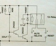
I didn't show the rest of the circuit because it was irrelevant and complicates the delay circuit. It consists of a rect. bridge and 1000u smoothing cap, the voltage is about 12V.
As to Aleph there is indeed a protection. I'll just quote Tortello from the other thread:
"In the Aleph 5 design, R15, R16 and Q4 form a sort of clipper to protect the active side's hexfets: R15 and R16 fix the maximum value of the current in each hexfet.
I think that this choice is not critical: the current limiter should not operate in "normal" conditions, and the high current capability of the power Hexfet (15A) assures a wide range of values.
In my Aleph 5 -hence with 3 Hexfets per side- biased with 3A -1A per Hexfet- I found a good mix with 220 Ohm for R15 and 150 Ohm for R16. The source resistor is 0.47Ohm.
The clipper operates at about 3.14A per Hexfet, 9.5A for the whole stack."
DC-Protection
at the moment I´m also running my amps without any protection except for the main fuse and nothing has happened (yet).
Since I´m not too comfortable with this I´ve made up a circuit that will protect in case of dc without a relay in the signal path. (made up as in drawn on a sheet of paper, no hardware yet)
In case of DC it will just short the output to ground and turn of the amp.
Has anybody ever heard relays producing music? I once tested my amp into a test load and could hear music. Since there was no speaker near I had a closer look and found that the output relay was acting as a (not very good speaker)
william
fcel said:2Bak,
I have read a thread dealing exactly on that copyright topic but I could not recall what was the resolution .... I think the discussion was still going on and I did not follow up on it.
Audio Electronics .... is that the new name for Audio Amateur?
Last but one. They've changed again, now its AudioXpress, which combines Audio Electronics, Glass Audio and Speaker Builder.
Check out www.audioxpress.com.
Jan Didden
Wuffwaff - relays and music
one of the "points" along the way to the invention of the telephone was Alexander Bell's listening to the chattering of telegraph relays. I guess that in a fashion he realized that if you could modulate the frequency of the relay you could produce a semblance of sound.
in the dark old days, pre-Apple, pre-Altair, even pre IBM 360 some of the technicicans at Ohio Bell Telephone (I imagine all the AT&T guys had too much time on their hands) were able to get the high-speed line printers (for printing bills) to "sing" -- kind of like a kazoo, but you get the point.
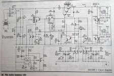
Since most of the interest seems to be in the realys and not the circuits , I present here a schematic of a protection system. I didn't build it because it seemed too complicated to me but it looks pretty interesting.
It has the following features:
Turn on delay with fast turn-off at power down
Amplifier offset shutdown
Adjustable thermal shutdown
Pilot light flasher indicating fault condition
Modular topology for easy adaptation
According to author "C1 had a significant influence on the amplifier's high-frequency performance. The reason for this is unclear, as I chose the capacitor value and type for optimum sound rather than for any numerical reasons".
, I present here a schematic of a protection system. I didn't build it because it seemed too complicated to me but it looks pretty interesting.It has the following features:
Turn on delay with fast turn-off at power down
Amplifier offset shutdown
Adjustable thermal shutdown
Pilot light flasher indicating fault condition
Modular topology for easy adaptation
According to author "C1 had a significant influence on the amplifier's high-frequency performance. The reason for this is unclear, as I chose the capacitor value and type for optimum sound rather than for any numerical reasons".
Attachments
folks,
Some power relays do infact produce measurable distortion.....see self (third edition).
This should'nt be a problem if the DC offset protection relay is in the mains supply to the transformer...a rather good idea as the woofer in the average 'speaker should survive the supply caps ramping down through it......
protection circuitry built around a window detector should be quite straightforward....
Amplifier protection etc
Guys,
The "singing" of the relays comes from the load current through the contacts, so feeding the relay coil with a stabilized DC does not cure this. Mechanical vibrations in hardware as a result of (large) current is not new. I have had a case where output binding posts made noises when driving hi levels in low impedance speakers. In fact, these binding posts vibrated so much that they repeatedly loosened themselves. A kind of "inverse microphony"?
Jan Didden
- Status
- This old topic is closed. If you want to reopen this topic, contact a moderator using the "Report Post" button.
- Home
- Amplifiers
- Pass Labs
- Amplifier and speaker protection circuits