current limiting
I am not a fan of crowbar (i.e. put a triac at the back door) to produce a short at the output. For me that is for people who have run out of ideas and/or designed their amps to run only electrostatic speakers.
I am not much of a fan of agressive current limiting either - a soft clamping of the drive is fine ..but .....and here's the big but....... if you anticipate driving difficult inductive loads of the type that can produce phasor plots 35 degrees misphase between current and volts - such as KEF104/2 (5 drivers per unit + a very complex crossover) Reference or Magneplanars - B&W801's - causing a whacking amount of harmonic and assymmetric conditions - current limit is not what you need -- it's a bigger VA (i.e. more current) available in the supply.
So often have I seen medium sized power amplifiers strapped to insignificant power supplies - take the Quad 405 as an example. 2x 100W amplifiers on a transformer I would have rejected for a 50W - then because of this they current limited the thing to death because they feared their precious ESL63 electrostatics would get harmed otherwise. Instead of cutting in at extreme conditions the current limit was bouncing in and out during normal operation on my bench -- which is poor design quite frankly.
A strong philosophy for designing amplifiers is look through all the most difficult load conditions you anticipate you are going to drive - and design from that position. Designing by including and considering the important loads is just good craftmanship.
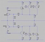
anyway that said... and just for good measure... here's a hopefully non-agressive current limit that may suit your plans. It shows a representation of your back stage and is designed to soft clamp the drive of the BD139/140 stage at extremes. The final tweak I would do on the bench into an inductive dummy load.
I am not a fan of crowbar (i.e. put a triac at the back door) to produce a short at the output. For me that is for people who have run out of ideas and/or designed their amps to run only electrostatic speakers.
I am not much of a fan of agressive current limiting either - a soft clamping of the drive is fine ..but .....and here's the big but....... if you anticipate driving difficult inductive loads of the type that can produce phasor plots 35 degrees misphase between current and volts - such as KEF104/2 (5 drivers per unit + a very complex crossover) Reference or Magneplanars - B&W801's - causing a whacking amount of harmonic and assymmetric conditions - current limit is not what you need -- it's a bigger VA (i.e. more current) available in the supply.
So often have I seen medium sized power amplifiers strapped to insignificant power supplies - take the Quad 405 as an example. 2x 100W amplifiers on a transformer I would have rejected for a 50W - then because of this they current limited the thing to death because they feared their precious ESL63 electrostatics would get harmed otherwise. Instead of cutting in at extreme conditions the current limit was bouncing in and out during normal operation on my bench -- which is poor design quite frankly.
A strong philosophy for designing amplifiers is look through all the most difficult load conditions you anticipate you are going to drive - and design from that position. Designing by including and considering the important loads is just good craftmanship.
anyway that said... and just for good measure... here's a hopefully non-agressive current limit that may suit your plans. It shows a representation of your back stage and is designed to soft clamp the drive of the BD139/140 stage at extremes. The final tweak I would do on the bench into an inductive dummy load.
Attachments
Last edited:
anyway that said... and just for good measure... here's a hopefully non-agressive current limit that may suit your plans. .
Indeed, it can be very agressive if the Vas is not current limited.
Sekhar, don't rush into this. There are a few other things to look at that might result in an altogether better amplifier.
I am looking at your 1st circuit diagram which is what I assume we are talking about. You are using a CFP output stage. Since the 3055 and 2955 are SLOW devices, you will run into stability problems and this will make compensation much more difficult, and/or you are going to have to reduce th eloop gain uncessarily in my view. Why dont you try a triple 'T' on the output. A much better solution all round.
Can you publish your latest circuit diagram?
I am not a fan of crowbar (i.e. put a triac at the back door) to produce a short at the output. For me that is for people who have run out of ideas and/or designed their amps to run only electrostatic speakers.
I am not much of a fan of agressive current limiting either - a soft clamping of the drive is fine ..but .....and here's the big but....... if you anticipate driving difficult inductive loads of the type that can produce phasor plots 35 degrees misphase between current and volts - such as KEF104/2 (5 drivers per unit + a very complex crossover) Reference or Magneplanars - B&W801's - causing a whacking amount of harmonic and assymmetric conditions - current limit is not what you need -- it's a bigger VA (i.e. more current) available in the supply.
So often have I seen medium sized power amplifiers strapped to insignificant power supplies - take the Quad 405 as an example. 2x 100W amplifiers on a transformer I would have rejected for a 50W - then because of this they current limited the thing to death because they feared their precious ESL63 electrostatics would get harmed otherwise. Instead of cutting in at extreme conditions the current limit was bouncing in and out during normal operation on my bench -- which is poor design quite frankly.
A strong philosophy for designing amplifiers is look through all the most difficult load conditions you anticipate you are going to drive - and design from that position. Designing by including and considering the important loads is just good craftmanship.
anyway that said... and just for good measure... here's a hopefully non-agressive current limit that may suit your plans. It shows a representation of your back stage and is designed to soft clamp the drive of the BD139/140 stage at extremes. The final tweak I would do on the bench into an inductive dummy load.
Questions like that has been arround the forum for ages now ...... funny thing is that one dislikes VI limiters of any form and other has to design an amplifier that is cost effective so overdesign is out of the question
the inovation will be to see if there is any other way to serve both
* keep the amp safe
* keep the cost reasonable
or in otherways share between comercial amps and high end amps
the single slope VI limiter shown by phaselocked loop will operate only in the condition where the load goes below 1E or there is a short circuit correct me if i am wrong.......
other wise it should cause no current limition for 4 or 8 E load.
I need help in calculating the values for the resistor so that the VI limiter starts working from 2.5E load .....
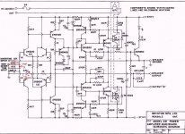
Current Circuit Diagram
SLONES MULTISLOPE VI LIMITER
Is it wise to use multislope vi limiter shown in above circuit if so how to calculate the values of resistor ?????????/
regards sekhar
other wise it should cause no current limition for 4 or 8 E load.
I need help in calculating the values for the resistor so that the VI limiter starts working from 2.5E load .....
Current Circuit Diagram
An externally hosted image should be here but it was not working when we last tested it.
SLONES MULTISLOPE VI LIMITER
An externally hosted image should be here but it was not working when we last tested it.
Is it wise to use multislope vi limiter shown in above circuit if so how to calculate the values of resistor ?????????/
regards sekhar
Hi,
these are all I limiters. The V part of the IV limiting is omitted. Except the Bryston with the 18k giving some V element. But where is the other half of their limiter? Or is it not needed?
All semiconductors can pass a short term transient of very much higher current than they can for continuous signals.
The IV limiter implementation must take account of this transient ability.
If it does not allow high current transients to pass unlimited then ythe designer is wasting some of the resource that has been installed.
For sound quality reasons alone the IV limiter must pass all valid signals to all valid loads.
The limiter should ONLY be allowed to limit output when the current/voltage falls outside the pass definition.
Last edited:
Hi,
these are all I limiters. The V part of the IV limiting is omitted. Except the Bryston with the 18k giving some V element. But where is the other half of their limiter? Or is it not needed?
All semiconductors can pass a short term transient of very much higher current than they can for continuous signals.
The IV limiter implementation must take account of this transient ability.
If it does not allow high current transients to pass unlimited then ythe designer is wasting some of the resource that has been installed.
For sound quality reasons alone the IV limiter must pass all valid signals to all valid loads.
The limiter should ONLY be allowed to limit output when the current/voltage falls outside the pass definition.
I agree Andrew. For an example of a true V-I limiter (also called Safe Operating Area - SOA limiter) see http://www.linearaudio.nl/SOA-2.htm .
jd
Questions like that has been arround the forum for ages now ...... funny thing is that one dislikes VI limiters of any form and other has to design an amplifier that is cost effective so overdesign is out of the question
the inovation will be to see if there is any other way to serve both
* keep the amp safe
* keep the cost reasonable
or in otherways share between comercial amps and high end amps
As I said in my post - I'm not a fan of any of them. It's like buying a BMW 6 series at 500Bhp and limiting it to only 300. Knowing full well the engine is awesomely designed to take it anyway and you'll probably never need all that power - and you certainly wont use it in normal operation anyhow. I think with current technology and intelligent design - it's not really necessary.
So why not design the engine to take the hammering? I find more satisfying challenges in combatting noise and distortion.
I do agree to u phaselocked loop but even if u make the best of the amp with no protection in it wat is the meaning one short circuit and every thing goes to hell.......... I just want to make an amp with good sonics and protection so that it can withstand the harshest of the use............
"this is the reason why manfucturers speed limit the engine so that it can used with consistency for a long period of time............."
Any suggestion with VI limiters shown in page 3....!!!!!!!!!!!\
Regards
Sekhar
"this is the reason why manfucturers speed limit the engine so that it can used with consistency for a long period of time............."
Any suggestion with VI limiters shown in page 3....!!!!!!!!!!!\
Regards
Sekhar
anyway that said... and just for good measure... here's a hopefully non-agressive current limit that may suit your plans. It shows a representation of your back stage and is designed to soft clamp the drive of the BD139/140 stage at extremes. The final tweak I would do on the bench into an inductive dummy load.
This is popular and used by many so guess it is okay and nice for someone to post it. Around here we call that circuit "the always fail blow up the amplifier circuit." If it is going to be real current limit the circuit should track the SOA (safe operating area) of the transistor or transistors in parallel.
"the always fail blow up the amplifier circuit."
DIDnt quite understand wat do mean by it kingly clarify ...........
NEways any help on multislope VI limiter shown in the previous page ........???????????/
Regards
Sekhar
Member
Joined 2009
Paid Member
I can't for the life of me see why BMW would put a limit like that in place unless it was either a legal-liability issue or plain old marketing **. But in DIY I personally don't care to consider VI limiters because I'm not making a commercial amp, its for me, to be used under conditions I prescribe and so I feel there's no need to compromise the simplicity of the design or risk any kind of negative consequences of using limiters.
EDIT: Interesting, the forum software has replaced the initials "b" followed by "s" with two **
EDIT: Interesting, the forum software has replaced the initials "b" followed by "s" with two **
I can't for the life of me see why BMW would put a limit like that in place unless it was either a legal-liability issue or plain old marketing **. But in DIY I personally don't care to consider VI limiters because I'm not making a commercial amp, its for me, to be used under conditions I prescribe and so I feel there's no need to compromise the simplicity of the design or risk any kind of negative consequences of using limiters.
EDIT: Interesting, the forum software has replaced the initials "b" followed by "s" with two **
Exactly --I have the same philosophy - and when designed specific to load one can develop a lot more load tolerance, dispensing with limiters entirely.
And yes BMW did restrict HP on their V10 M6 - a limiter that can be shut off by the driver to release all the horses. A paradox.
re adjust ofset and idle ....but another thing to do will be to make some tests with diferent bias high or low start with 25-35 and you may try up to 120 given as a fact that you have enough and efficient cooling
that will be also very interesting to make listeng tests ( extensive ) with transitor A or B to see what fits in to your ears best and if you vcan see diference between trs
be aware that there is a lot of 1943 5200 fake arround here and there meaning that you need to be sure about the quality before you start pushing them around
modern transitors might work better with lower miller cap values you may also want ot expirament there but from a safe point of view only scope generator and testings will show you that
I luckly got 2SC5200 & 2SA1943 out here can i replace them in the original circuit is any change required ????????????????/
REgards
Sekhar
Ft is 10x that of the 3055 - being triple emitter diffused - well that helps on top end performance -- I've got no real experience with these but they do look promising
Last edited:
- Status
- This old topic is closed. If you want to reopen this topic, contact a moderator using the "Report Post" button.
- Home
- Amplifiers
- Solid State
- amp for everybody