The first huge advantage of using a precision unity gain inverter is the distortions created by the first amp tend to be canceled by the same effect in the second amp. This is not the case if the second amp is driven by a separate inverter. Both amps being identical the distortions add together when driven by an inverter op amp. Another problem with using an inverter op amp is the delay of the op amp is added to the second channel. This has time and time again been a problem for balance transmitters in audio such that a lot of fancy schemes have been developed in the past to cause the plus and minus outputs of balanced transmitters (found on mixers and lots of pro audio gear) to remain in the same phase and amplitude relationship over the audio band. A simple inverting op amp on one side turns out to just be plain wrong.[snip]
Sorry, I cannot agree to this. The distortions will only cancel if they are the same and in opposite phase, and in general that is unlikely. You may get lucky, and some of the odd harmonics may cancel.
The idea that unity gain opamp inverters are somehow problematic in what you call 'balanced transmitters' is simply incorrect. A unity gain opamp stage has a gain accurately 0.9999999 or 1.000001. The gain and phase will be flat over much more than the audio band, much more than the power amps to be driven. At any rate, even if the gain is off like 'only' 0.95 or 1.10 there is still no distortion or whatever, only the clipping of the bridged output will become asymmetric. There are no 'fancy schemes', in effect it is one of the most simple and high performance circuits you can think of.
jd
Last edited:
Sorry, I cannot agree to this. The distortions will only cancel if they are the same and in opposite phase, and in general that is unlikely. You may get lucky, and some of the odd harmonics may cancel.
The idea that unity gain opamp inverters are somehow problematic in what you call 'balanced transmitters' is simply incorrect. A unity gain opamp stage has a gain accurately 0.9999999 or 1.000001. The gain and phase will be flat over much more than the audio band, much more than the power amps to be driven. At any rate, even if the gain is off like 'only' 0.95 or 1.10 there is still no distortion or whatever, only the clipping of the bridged output will become asymmetric. There are no 'fancy schemes', in effect it is one of the most simple and high performance circuits you can think of.
jd
Have you actually tried this in real test bench with amplifier or are you speaking theory off the cuff? Try this with real amplifier please and discover the facts.
Also note the second amplifier is inverting so distortion cancellation occurs. To cancel the distortion well the gains must be precision matched. Further the load is in the feedback loop. An advantage which cannot be understated.
As for fancy schemes of balanced receiver transmitters- you are clearly not educated in the practice as there have been many papers and much discussion on this very subject matter in the journals over many years leading to a lot of different circuits in use professionally for non-transformer balanced receivers and transmitters.
Here is links to one pile of references of actual design:
SSM2141 | High Common-Mode Rejection Differential Line Receiver | Audio Signal Processors | Audio/Video Products | Analog Devices
SSM2143 | -6 dB Differential Line Receiver | Audio Amplifiers | Audio/Video Products | Analog Devices
Please read the application notes and look up the reference materials listed therein if you care to educate yourself in this subject matter.
Have you actually tried this in real test bench with amplifier or are you speaking theory off the cuff? Try this with real amplifier please and discover the facts.
Also note the second amplifier is inverting so distortion cancellation occurs. To cancel the distortion well the gains must be precision matched. Further the load is in the feedback loop. An advantage which cannot be understated.
Here is links to one pile of references of actual design:
SSM2141 | High Common-Mode Rejection Differential Line Receiver | Audio Signal Processors | Audio/Video Products | Analog Devices
SSM2143 | -6 dB Differential Line Receiver | Audio Amplifiers | Audio/Video Products | Analog Devices
Please read the application notes and look up the reference materials listed therein if you care to educate yourself in this subject matter.
The links you re quoting are also theorical works...
Say that we have two amplifiers perfectly identical with the same
distorsions...
Let s call amplifier A output signal V + D , D being the distorsion..
Amplifier B being identical, its output will be V + D as well.
Let s introduce a perfect inverter with unity gain at the input
of amplifier A..
Amplifier A output will be -V-D; that is exactly the same as amp B
apart from the phase that is inverted by 180°...
In fact, there will be some distorsion cancelling only if the amps
have differerent transfer functions.
As pointed by janneman,it works only if you are extremely lucky.
Your distorsion cancellation occur only if the amps are not exactly
the same, but even if it possible, statistically, the distorsion ratio
will not be improved..
That said, can you please give us some clues about your distorsion
cancelling sheme?.be assured that we are eager to learn about it..
The links you re quoting are also theorical works...
That said, can you please give us some clues about your distorsion
cancelling sheme?.be assured that we are eager to learn about it..
Those are links to real products, not theory. The references listed in the application notes are links to studies and theories.
I have clearly explained the working of the method such that anyone can do this. To quote John Curl "I wish my amps were this low in distortion." I have kindly provided the must useful method there is and you summarily reject it. I ask you, have you tried this? If the answer is no then you really have nothing to say. If you have tried this then you will see the fact that all I say is correct.
I have no more interest in arguing this method or result. I suggest you do this in a laboratory and discover the result first hand. Nothing I will say will change your mind. The result of very low distortion with much better sound and damping is clearly demonstrated in laboratory testing.
It doesn t take long to understand one thing :
Distorsion caused by badly implemented ground nodes is cancelled
when using a bridge scheme, as there s no more high level currents running
through the ground planes, only on the Vcc lines...
So a very bad layout that would produce vast amounts of distorsion
will work reasonably well if the same layout is used in a bridge configuration..
This is probably the main reason of the differences you re quoting, as mathematicaly,
the cancellations you re talking about have no other explanation than this one..
I m curious to know janneman s expertise about this...
It doesn t take long to understand one thing :
Distorsion caused by badly implemented ground nodes is cancelled
when using a bridge scheme, as there s no more high level currents running
through the ground planes, only on the Vcc lines...
So a very bad layout that would produce vast amounts of distorsion
will work reasonably well if the same layout is used in a bridge configuration..
This is probably the main reason of the differences you re quoting, as mathematicaly,
the cancellations you re talking about have no other explanation than this one..
I m curious to know janneman s expertise about this...
Yes that is possible, the ground currents are much less and that can lead to overall better sound. Also the power supplies are now loaded more equally and that also (depending on the implementatioon) can have a better effect, although the supply currents are larger so the total effect may may not be large.
It's difficult to give general rules here, it is so dependent on realization.
jd
Reality versus Empirical Testing and Theory
Sorry sirs, you seem to be stuck on the thought the models represent all distortions of the amplifiers. This is just plainly and clearly not true. Consider that amplifiers which test similarly in distortion and model nearly the same result is grossly different listening experience. Is this true? Of course! To make matters more confusing there are almost no speakers available with distortions matching amplifiers. Indeed loudspeaker harmonic and intermodulation distortion are at least an order of magnitude greater than the amplifier. So how is it possible these very low distortion amplifiers all built to similar method and power sound so different using speakers which distort ten times as much? I will leave that for another time as it is clearly the case and therefore obviously true.
If you are truly interested, make the test with your favorite amps and discover the facts. These distortions are not about bad grounding or other layout problems. The method greatly reduces these poorly documented distortions grossly improving listening experience and clarity. I mean this is so obvious when tried there can be no doubt of the effectiveness. Please try it and then discuss!! Possibly you will be the one to define the mechanism of distortion. Good luck to your task of that.
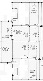
FYI- I have build about 250 different power amplifier topologies using identical power supplies and similar layout techniques. These amps were all tested for many things what was found is most amps really do not work that well. The result of this extensive testing is two different topologies which work pretty well. The rest of the 250- not so. No I shall not release this information in general however I will show the result of output stage configuration used in all amplifiers now.
It doesn t take long to understand one thing :
Distorsion caused by badly implemented ground nodes is cancelled
when using a bridge scheme, as there s no more high level currents running
through the ground planes, only on the Vcc lines...
So a very bad layout that would produce vast amounts of distorsion
will work reasonably well if the same layout is used in a bridge configuration..
This is probably the main reason of the differences you re quoting, as mathematicaly,
the cancellations you re talking about have no other explanation than this one..
I m curious to know janneman s expertise about this...
Sorry sirs, you seem to be stuck on the thought the models represent all distortions of the amplifiers. This is just plainly and clearly not true. Consider that amplifiers which test similarly in distortion and model nearly the same result is grossly different listening experience. Is this true? Of course! To make matters more confusing there are almost no speakers available with distortions matching amplifiers. Indeed loudspeaker harmonic and intermodulation distortion are at least an order of magnitude greater than the amplifier. So how is it possible these very low distortion amplifiers all built to similar method and power sound so different using speakers which distort ten times as much? I will leave that for another time as it is clearly the case and therefore obviously true.
If you are truly interested, make the test with your favorite amps and discover the facts. These distortions are not about bad grounding or other layout problems. The method greatly reduces these poorly documented distortions grossly improving listening experience and clarity. I mean this is so obvious when tried there can be no doubt of the effectiveness. Please try it and then discuss!! Possibly you will be the one to define the mechanism of distortion. Good luck to your task of that.
FYI- I have build about 250 different power amplifier topologies using identical power supplies and similar layout techniques. These amps were all tested for many things what was found is most amps really do not work that well. The result of this extensive testing is two different topologies which work pretty well. The rest of the 250- not so. No I shall not release this information in general however I will show the result of output stage configuration used in all amplifiers now.
Attachments
hi everybody i finally understood one thing that bridging is nt for me I am simplely happy with my simple amp with valuable modification from all of u............ I need more experience to do such serious stuff ..............neways thanks to all of u for such valuable information i have already made an amp which is happily driving 150W in 4E next time i will make something bigger and better.................
regards
sekhar
regards
sekhar
- Status
- This old topic is closed. If you want to reopen this topic, contact a moderator using the "Report Post" button.
- Home
- Amplifiers
- Solid State
- amp for everybody